5 • HARDWARE CONFIGURATION
6 • WORK MODE
12
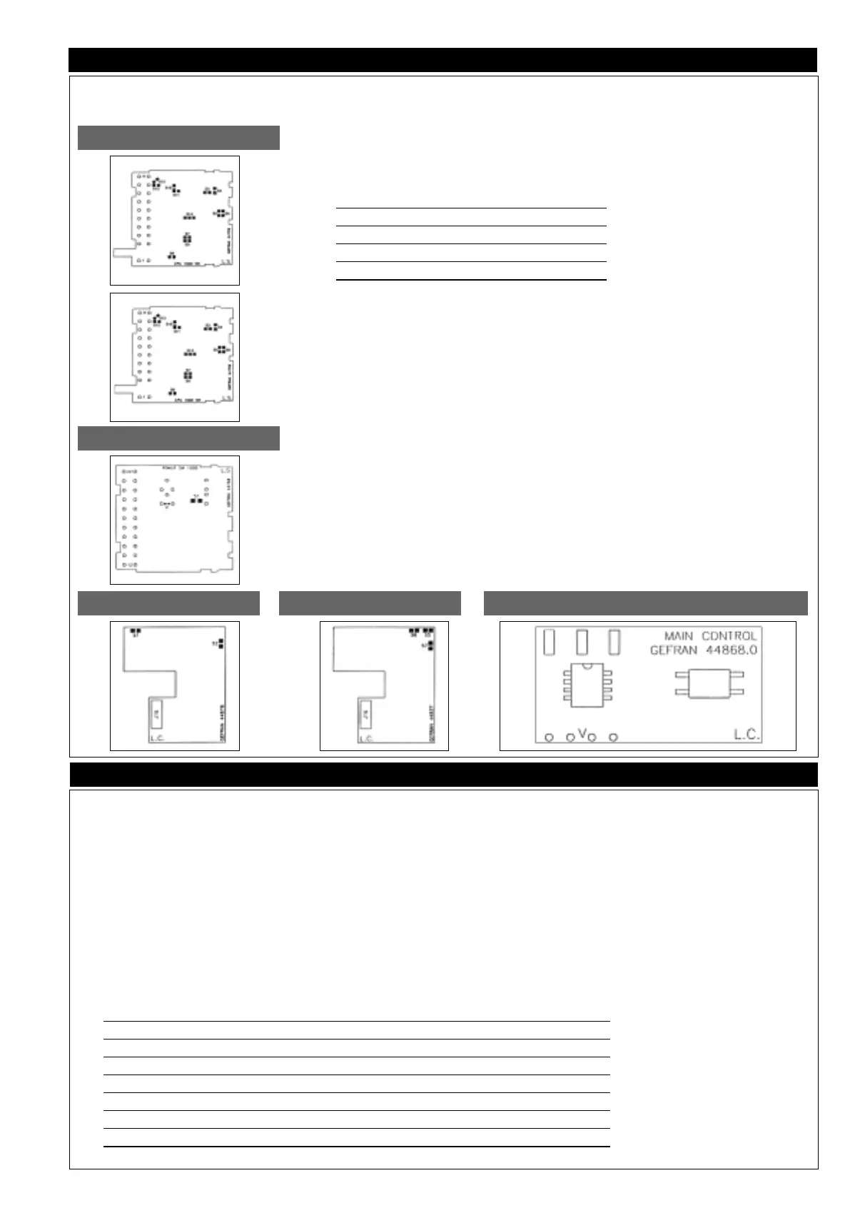
Input Board
Hardware protection
To remove the electronic part of the case, loosen the front screw until release, then remove by hand. Configuration is performed on the input board, the output/power board, and
on the optional board.
Input board
The input board has jumpers to enable/disable configuration and calibration as described
in the following table:
Description Jumper Soldered
Position jumpers
(comp.side) (solder side)
Config. enabled 3 3 closed *
Config. disabled 7 or 8 3 open *
Calibraz. enabled 6 6 closed *
Calibraz. disabled 7 or 8 6 apen *
* jumper on solder side as alternative to jumper on component side
The instrument is supplied with disabled configuration and calibration.
The input from probe RTD Pt100 (type 11) calls for jumper S3 open, S9 closed.
Optional alarms 2 and 3
Select N.O./N.C. alarm relay contacts 2/3.
Normally, alarms 2 and 3 are supplied N.O.; for the N.C. version, you have to manually remove the N.O. jumpers and
install the N.C. jumpers (jumpers S10/S11, S12/S13 on input board, solder side).
Output/power board
Main output D2
When output D2 is used, we advise you to exclude the MAIN relay by manually removing jumper
S1. To have the output
in voltage in case of continuous output, install jumper V.
RS485 serial output (code 2 in order code)
The RS485 serial line can be polarized by installing soldered jumpers S5, S6 and S7 on the solder side of the board.
The transmission distance of serial output RS422/RS485 aches 500 meters with a maximum of 32 instruments connect-
ed. For line lengths exceeding 50 meters, and when impedance for line termination is needed, this is available inside the
instrument.
Termination will have to be performed inside the instrument that is farthest from the serial connection chain.
Optional continuous MAIN output control board
For output in voltage, install jumper marked V.
(See power output board)
Power Output Board
Optional C.L. Serial Board
Optional RS485 Board
Optional continuous MAIN output control board
Introduction
Work mode lets you monitor the main process quantities: process variable, load cur-
rent, control output power, while output state (MAIN and alarms) is signaled by their
LEDs. It also lets you display and set the setpoints and alarms.
You can scroll the seven work processes (see table below) by means of the F key. Use
the Raise and Lower keys to set the setpoints and alarms. Confirm the set value by
pressing the F key (if the key is not pressed, the value will be confirmed automatically
10 seconds after the last change).
Enabling the various phases depends on the hardware and software configuration and
on the software protection level that is set (Pro code in CFG.2 procedure). In minimum
configuration, only phases 0 and 1 are available.
At power-on, after the display has finished flashing, the instrument goes to work mode
phase 0 (automatic start), or to phase 6 (manual start).
Specific combinations of keys let you switch between automatic and manual, turn the
software off and on, start or interrupt self-tuning. Work mode is the starting point for
access to Programming, Configuration and Calibration phases.
Display of process variable, load current, output power.
Setting setpoint and alarms
AUTO/MAN function
Software On/Off function
Start/Stop self-tuning
Software release
Error messages and signals
Power on
Sequence of phases in work mode
Work phase Upper diplay Lower display Phase indication Notes
0 Process variables Control setpoint* Note 1
1 Process variables Alarm limit 1 * Led AL1 flashing Note 2
2 Process variables Alarm limit 2 * Led AL2 flashing Note 2
3 Process variables Alarm limit 3 * Led AL3 flashing Note 2
4 CT input value Alarm limit HB * Letter A flashing Note 3
5 Process variables CT input value Letter A steady Note 4
6 Process variables Auto/Man power in output Lettera P steady/flashing Note 5
* settable value, return to work phase 0 after 10 seconds.
 Loading...


