This section contains a list of the Technical Specifications for the 1200/1300 Controllers
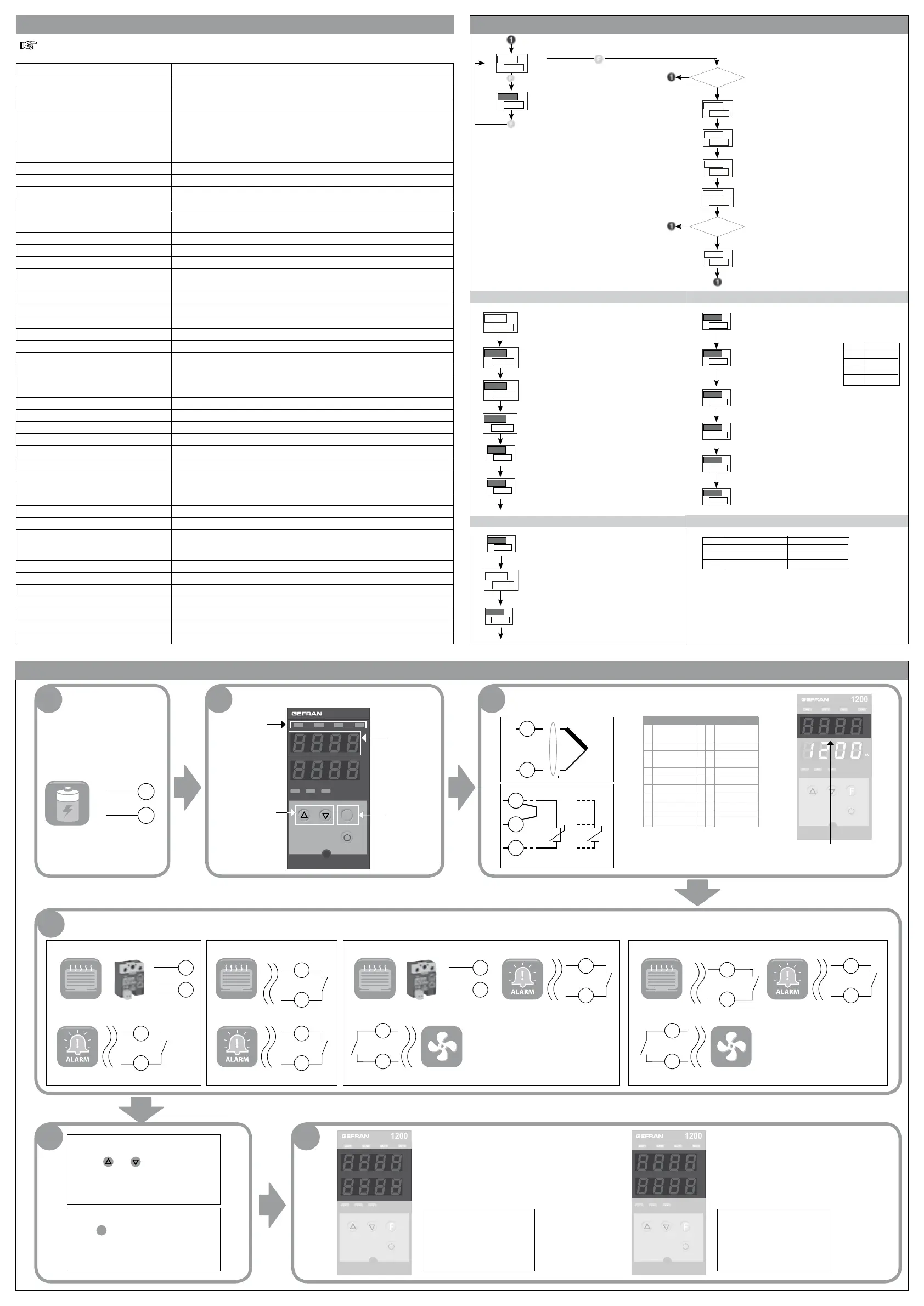
5 • TECHNICAL SPECIFICATIONS
7• QUICK START GUIDE
6 • “EASY” PROGRAMMING and CONFIGURATION
• CFG • InP
• Pro
1 2 3
Output
states
Change
parameter
value
Scan menu/
parameters
Sbr- Err
for sensor not
connected or
in short
~
TC
+
-
2
1
Pt100
3
1
2
T
T
If the correct value of the input (for
example, temperature) is not
displayed, check the connections.
11
~
10
4
1200/1300-R-D-X-X-X-X-X
6
-
+
5
6
-
+
5
8
7
8
7
8
7
1200/1300-R-D-R-X-X-X-X 1200/1300-R-R-R-X-X-X-X
6
5
5 6
12
13
12
13
Menu
3 sec.
EASY Configuration/Programming
Standard for instrument with 2 Outputs:
OUT1 = AL1 / OUT2 = MAIN HEAT
In the EASY configuration, the general navigation
flow shown at the end of Section 3 - Functions
is considerably simplified, as illustrated in the
following figure.
For a detailed description of the parameters,
the complete manual is available for download
from the website www.gefran.com
Level 1 display
PV
SV
39.9
40.0
AL.I
PV
SV
Soglia allarme 1
(punti scala)
Jumper S4 on soldered side
of CPU board
PV
SV
F
G
G
---
OK
S4 ON ?
NO
PV
SV
n
I
P.
---
PV
SV
v
0
t
---
PV
SV
A
P
S
99
Configuration
Inputs Setting
Outputs Setting
Password
PV
SV
r
P
o
---
OK
PAS = 99 ?
NO
Protection code
1.0
h.Pb
PV
SV
4.00
h.It
PV
SV
Proportional band for heating
or hysteresis for ON/OFF control
[0 ... 999.9] % f.s.
Integral time for heating
[0.00 ... 99.99] min.
1.00
h.dt
PV
SV
100.0
h.P.K
PV
SV
- 1
KY.i
PV
SV
MAX power limit for heating
[0.0 ... 100.0] %
Hysteresis for Alarm 1
[±999] punti scala
Derivative time for heating
[0.00 ... 99.99] min.
PV
SV
t
S.
v
0
Enabling self-tuning, autotuning,
softstart (**)
• Out
0
tYP
PV
SV
Type of probe, signal, custom linearization
enabling and main scale input
(See input connection)
Decimal Point Pos.
for Input Scale
DP.S Format
0 xxxx
1 xxx.x
2 xx.xx (*)
3 x.xxx (*)
Main Input Scale MAX Limit Valore Min..Max value
assigned to input selected with the TYP parameter
Lower limit for SP and absolute alarms LO.S ... KI.S
Upper limit for SP and absolute alarms LO.S ... KI.S
Main Input Scale MIN Limit Min..Max value assigned
to input selected with the TYP parameter
0
dP.S
PV
SV
0
Lo.S
PV
SV
1000
Ki .S
PV
SV
0
LoL
PV
SV
1000
Ki .L
PV
SV
0
AI.t
PV
SV
20
Gt.2
PV
SV
PV
SV
L.
r
2
1
SV Alarm type 1
If more alarms are enabled the functionality is valid
also for (A2t, A3t).
OUT 2 Cycle time (HEAT or COOL)
[1 ... 200] sec.
the same setting range is valid also for
Ct1, Ct3, Ct4.
OUT 1
Allocation of reference signal
If more outputs are available (rL2, rL3, rL4)
PRO Display Modification
0 SP, alarms SP, alarms
1 SP, alarms SP
2 SP
By adding the following amounts to the values shown in the table a
series of supplementary functions can be enabled:
+4: to disable INP, 0VT
+8: to disable [FG
+128: to enable the display of all the parameters and menus.
1200
ouT1
ouT2 ouT3 ouT4
PV
SV
1200
1200
L1 L2 L3
F
1200
ouT1
ouT2 ouT3 ouT4
PV
SV
PV
1200/1300-R-R-X-X-X-X-X
8
7
6
5
1200
ouT1
ouT2 ouT3 ouT4
PV
SV
PV
SV
1200
ouT1
ouT2 ouT3 ouT4
PV
SV
PV
SV
Display 2x4 digits, green, height 10 and 7mm
Keys 4 mechanical keys (Man/Auto, INC, DEC, F)
Accuracy 0.2% f.s. ±1 at 25°C room temperature
Thermal drift 0.005% f.s. / °C
Main input (configurable digital filter)
TC, RTD, PTC, NTC 60mV,1V Ri≥1MW;
5V,10V Ri≥10KW; 20mA Ri=50W
Sampling time 120 msec.
Type TC (Thermocouples) (ITS90) J, K, R, S, T (IEC 584-1, CEI EN 60584-1,60584-2)
a custom linearization can be inserted
Cold junction error 0.1° / °C
RTD Type (temperature resistance) (ITS90) Pt100 (DIN 43760), JPT100
Max. line resistance for RTD
20W
PTC Type / NTC Type
990W, 25°C / 1KW, 25°C
Safety detection of short circuit or opening of probes, LBA alarm,
HB alarm
°C / °F selection configurable from faceplate
Linear scale ranges -1999...9999, with configurable decimal point position
Controls Pid, Autotune, on-off
pb - dt - it 0.0...999.9 % - 0.00...99.99 min - 0.00...99.99 min
Action heat / cool
Control outputs on / off, continuous
Max. power limit heat / cool 0.0...100.0 %
Cycle time 0...200 sec
Main output type relay, logic, continuous (0...10V / 4...20mA)
Softstart 0.0...500.0 min
Fault power setting -100.0...100.0 %
Automatic blanking maintains PV value display, optional exclusion
Configurable alarms up to 3 alarm functions assignable to an output and configurable of
type: maximum, minimum, symmetrical, absolute/relative, LBA, HB
Alarm masking exclusion during warm up, memory, reset from faceplate and/or contact
Type of relay contact
NO (NC), 5A, 250V/30Vdc cosj=1
Logic output for static relays 24V ±10% (10V min at 20mA)
Triac output 20...240Vac ±10%, 1A max, inductive and resistive load I2t = 128A
Transmitter power supply 24Vdc, max 30mA short-circuit protection
Analogue retransmission
10V/20mA Rload max 500W 12 bit resolution
Digital inputs
Ri = 4,7KW (24V, 5mA) or from terminal not supplied with power
Serial interface (optional) RS485, isolated
Baudrate 1200, 2400, 4800, 9600, 19200
Protocol Gefran CENCAL / MODBUS
Amperometric input option
C.T. 50mAac, 50/60Hz, Ri = 10W
Power supply (switching type) (standard) 100...240Vac/dc ±10% max 18VA
(optional) 11...27Vac/dc ±10% max 11VA
50/60Hz
Faceplate protection IP65
Working / Storage temperature range 0...50°C / -20...70°C
Relative humidity 20...85% Ur non-condensing
Environmental working conditions for indoor use, altitudes up to 2000m
Installation panel, removable faceplate
Installation specifications installation category II, pollution level 2, double isolation
Weight 160 g (complete version)
FIRST STEPS DESCRIPTION 1.INPUT CONNECTION
· Open the package
· Power up the device according
to the “Supply” information on
the label.
Electrical
energy
Pt100 3
wires
PTC / NTC /
Pt100 2 wires
Input programming
-
tyP parameter
- On
Inp menu
Input sensor
Sensor
type
Sensor
type
0 TC J °C 30 PT100 °C
1 TC J °F 31 PT100 °F
2 TC K °C 32 JPT100 °C
3 TC K °F 33 JPT100 °F
4 TC R °C 34 PTC °C
5 TC R °F 35 PTC °F
6 TC S °C 36 NTC °C
7 TC S °F 37 NTC °F
8 TC T °C 44 4...20 mA
9 TC T °F 46 0...10 V
CONNECTING OUTPUTS ACCORDING TO ORDER CODE
Alarm
Alarm Alarm
Alarm
HeatingHeatingHeatingHeating
Solid state
power unit
Solid state
power unit
Cooling
To enable the Cooling output it
is necessary to set the following
parameters
[tr= 8 (krd menu)
rl.3 =1 (0vt menu)
Cooling
To enable the Cooling output it
is necessary to set the following
parameters
[tr= 8 (krd menu)
rl.3 =1 (0vt menu)
PROGRAMMING SP
Use the and buttons to set the
control reference value (SV) on the main
page. (see point 2 DESCRIPTION)
PROGRAMMING AL1
Press
F
once on the main page: you
will see AL.1, which lets you change the
reference value of Alarm 1.
CHECKING OUTPUT OPERATION
H: LED OUT2 OFF
AL1: LED OUT1 ON
C: LED OUT3 ON
Set SP=AL1= PV+10,
wait 20 seconds, and check the
state of the LEDs.
Set SP=AL1= PV-10,
wait 20 seconds, and check the
state of the LEDs.
H: LED OUT2 ON
AL1: LED OUT1 OFF
C: LED OUT3 OFF
 Loading...