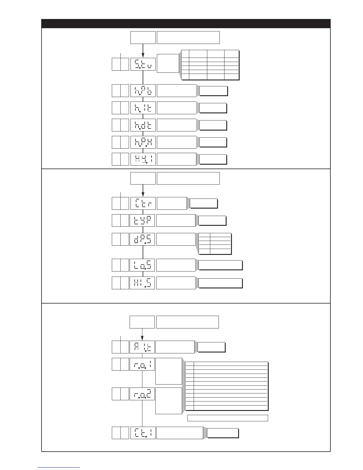
OUT 1
Attribution of
reference signal:
HEAT, COOL,
AL1, AL2, AL3
+ 16 for logic level denied at output
OUT 2
Attribution of
reference signal:
HEAT, COOL,
AL1, AL2, AL3
r.o.x MAIN logic output function, relay (OUT1)
0 HEAT (heating control output)
1 COOL (cooling control output)
2 AL1 - alarm 1
3 AL2 - alarm 2
4 AL3 - alarm 3 [A.Hb mod. 401])
5-
6 LBA - alarm LBA
7 (AL1) OR (AL2)
8 (AL1) OR (AL2) OR (AL3 [A.Hb mod. 401])
9 (AL1) AND (AL2)
10 (AL1) AND (AL2) AND (AL3 [A.Hb mod. 401])
2
0
Cycle time OUT1 relay or
logic = HEAT or COOL
0. ... 200 sec10
See table on Out
menu
Alarm type 1
0
Out
Output settings
Default Custom
Configurat.
12
See table on InP
menu
See table on InP
menu
5 • Standard Configuration Menu
Enable
selftuning,
autotuning,
softstart
Proportional heating
range or hysteresis in
regulation ON/OFF
Integral heating time
Derived heating time
Maximum limit heating
power
S.tu Autotuning Selftuning Softstart
continuous
0NO NO NO
1 YES NO NO
2 NO YES NO
3 YES YES NO
4 NO NO YES
0 ... 999,9% f.s.
0,00 ... 99,99 min
0,00 ... 99,99 min
0,0 ... 100,0%
0
10.0
4.0
1.0
100.0
Default Custom
Configurat.
Control type
[0...11]
22
Type of sensor, signal
and main input scale
0
Position of decimal point
for main input scale
Minimum limit of main
input scale
Maximum limit of main
input scale
dP.S Format
0 xxxx
1 xxx.x
2xx.xx (*)
3x
.xxx (*)
min...max of input
selected in tyP
min...max of input selected
in tyP
0
0
1000
CFG
Setting Parameters
InP
Input settings
Default Custom
Configurat.
± 999
scale points
Hysteresis for alarm 1
-1