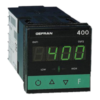
Do you have a question about the gefran 400 and is the answer not in the manual?
| Output Type | Relay, SSR, Analog |
|---|---|
| Control Type | PID |
| Input Type | Thermocouple, RTD |
| Power Supply | 24V AC/DC |
| Communication | RS485 Modbus |
| Dimensions | 48x48 (1/16 DIN) |
Explains the meaning of various graphical symbols used in the manual.
Provides an overview of the controller's features, input/output capabilities, and user interface.
Details the connection terminals for power supply, inputs, and outputs on the instrument's back.
Lists important warnings and checks to perform before installation and use.
Instructions for connecting the instrument's power supply, including safety requirements.
Covers safety standards, EMC compliance, and general guidelines for safe installation.
States conformity with European directives for EMC and safety standards.
Specific recommendations for ensuring electromagnetic compatibility during installation.
Guidelines for powering the instrument from switchboards and ensuring separate lines.
Details on connecting analogue inputs, outputs, and relay outputs, including cable recommendations.
Describes the physical process of fitting the instrument into a control panel.
Safety and installation guidelines specific to mounting the controller in a panel.
Specifies acceptable environmental conditions like temperature and humidity for operation.
Details on wiring for current transformer inputs/outputs, including specific terminals.
Describes connections for DC current, DC voltage, and linear inputs, including sensor types.
Explains the wiring for the main power supply, standard and optional.
Explains the functions of the display, LEDs, and buttons on the controller's front panel.
Outlines the parameters related to control settings, tuning, and softstart.
Details parameters for configuring sensor types, input scales, and control types.
Describes parameters for assigning functions to outputs, including alarms and logic.
Explains how to navigate through the controller's menu levels and access parameters.
Introduces the main parameter groups (CFG, InP, Out, Prot) and their roles.
Details how to set up a password to restrict parameter access and modifications.
Specifies parameters for selecting control types (P, PI, PID, ON/OFF) and their modes.
Covers selecting sensor types (TC, RTD, PTC) and configuring input scales and formats.
Provides specific details for various sensor types like TC, RTD, PTC, Voltage, Current, and CT.
Explains how to assign and configure up to six alarms (absolute, relative, LBA, HB).
Details the operation and configuration of the HB alarm, often related to current transformer input.
Explains the HB alarm logic for load current variations, including ON/OFF times and conditions.
Illustrates normal and symmetrical absolute alarms with hysteresis and time delays.
Illustrates deviation alarms, including symmetrical ones, with hysteresis and logic.
Step-by-step guide to manually calculate and set PID parameters for optimal control.
Instructions on how to deactivate and reactivate the controller unit using specific key combinations.
Explains how the auto-tuning feature automatically seeks optimal PID parameters for process control.
Details the procedure for activating self-tuning at power-on to calculate PID parameters.
Explains the concept of proportional control and its effect on output and system response.
Lists specifications for the controller's display, input keys, and measurement accuracy.
Details input types (TC, RTD, PTC), scale ranges, and related resistances.
Covers safety requirements, EMC standards, and available control actions (Pid, Autotune, On-off).
Specifies power supply requirements, operating temperatures, humidity, and installation constraints.
Describes available current transformers for measuring current and their specifications.
Information on the interface cable for PC configuration and the included software.
Describes the functionality and specifications of the relay output board for OUT3.
Provides technical details for the relay output, including current ratings and protection.
Describes the functionality and specifications of the logic output board for OUT3.
Provides technical details for the logic output, including voltage and current limitations.
Describes the functionality and specifications of the current transformer input board for OUT3.
Provides technical details for the CT input, including accuracy and resistance.
 Loading...