7
81503D_MHW_400-401_12-2010_ENG
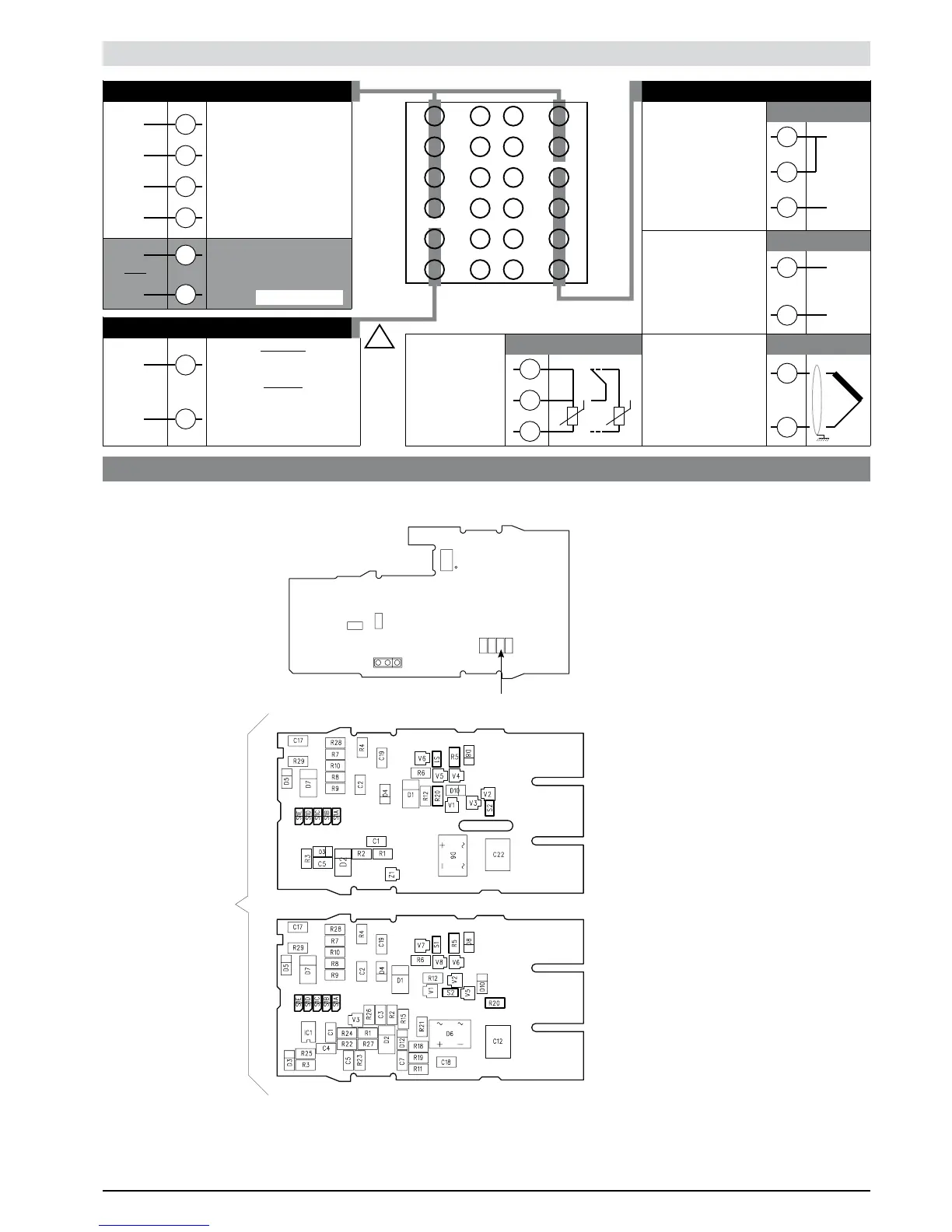
Electrical Connections
dc current
linear input
0 ... 20mA, 4 ... 20mA
• Linear (I)
4
1
2
-
+
• Linear (V)
• PTC / Pt100 2-3 wires
Standard:
100...240Vac ±10%
Optional
11...27Vac/dc ±10%
Max. power 10VA; 50/60Hz
• Current transformer outputs / inputs
+
-
Generic user-configurable
output
- relay 5A/250Vac
- logic
for OUT1 10V (6V/20mA)
Rout=220Ω
for OUT2 24V (10V at 20mA)
- relay 5A/250Vac
- logic 24V (10V a 20mA)
Current transformer
50mAac, 10Ω 50/60Hz
Available thermocouples:
J, K, R, S, T, B, E, N
- Respect polarities
- For extensions,
use compensated
cable appropriate for
thermocouple.
• Inputs
• TC
Use wires of
adequate thickness
(min. 1mm
2
)
PT100, PTC
6
5
4
3
2
1
7
8
9
10
11
12
18
17
16
15
14
13
19
20
21
22
23
24
2
1
3
1
2
dc voltage
linear input
0...60mV, 0...10V,
12...60mV, 2...10V
2
1
+
-
19
21
20
22
-
+
Out2 (Al1)
-
+
Out1 (Main)
• Power supply
23
24
~
~
TOP
6
5
-
+
Out3 (Al2)
C.T. input
only for mod. 401
!
PWR
Pt100 3 wires
PTC / Pt100 2 wires
T
T
Device structure: identification of boards
S4
S5
S6
S7
J9
TX
RX
GND
S9
S1
CPU BOARD (Sealing Side)
S6 = ON Enable Calibration
S6
power HV RR sealing side (HV RD)
power LV RR sealing side (LV RD)
for inverse OUT1: S2 = ON, remove R20
for inverse OUT2: S1 = ON, remove R5