( ..................................................\
, ,
, ,
, ,
:
"
-
~
"
",' ,
:
:
~"
~q;
,
."
:
\~
i~
:
,~'
:
~
\
\~
~
:."
........
.
~
:
.~:
,
~
\
\
..
.
..
\
~',~}
':
:
:
~
:
,
~.
\
:'~"
:
.
\'
"'\ \
1"
, ,
\
,
,
\
\
\
,
\
,
\
,
\
,
\
,
,
,
,
,
~
~,
..
'.'"
''
s
\
:
\,,~
.
..
"
....
.
..
"'~
\ , '
\
~~~~
...
-.~~~~,
...........
~
..\
l
"
_
;
~\
.....
·'
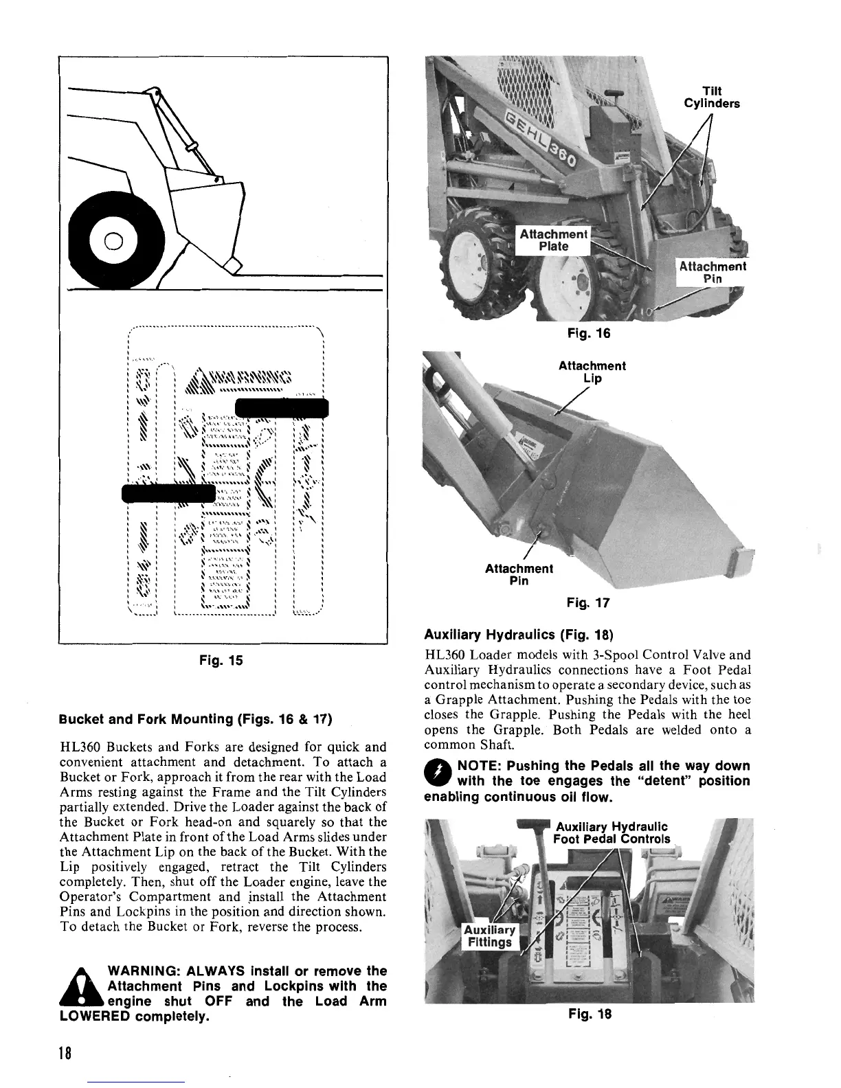
Fig. 15
Bucket and Fork Mounting (Figs. 16 & 17)
HL360 Buckets and Forks are designed for quick and
convenient attachment and detachment.
To
attach a
Bucket or Fork, approach
it
from the rear with the Load
Arms resting against the Frame and the Tilt Cylinders
partially extended. Drive the Loader against the back of
the Bucket or
Fork
head-on and squarely so that the
Attachment Plate in front
of
the Load Arms slides under
the Attachment Lip on the back
of
the Bucket. With the
Lip positively engaged, retract the Tilt Cylinders
completely. Then, shut off the Loader engine, leave the
Operator's Compartment and jnstall the Attachment
Pins and Lockpins in the position and direction shown.
To detach the Bucket or Fork, reverse the process.
A
WARNING: ALWAYS install or remove the
Attachment
Pins
and
Lockpins with the
engine shut OFF and the Load Arm
LOWERED completely.
Fig. 16
Fig.
17
Auxiliary Hydraulics (Fig. 18)
HL360 Loader models with 3-Spool Control Valve and
Auxiliary Hydraulics connections have a
Foot
Pedal
control mechanism to operate a secondary device, such
as
a Grapple Attachment. Pushing the Pedals with the toe
closes the Grapple. Pushing the Pedals with the heel
opens the Grapple. Both Pedals are welded onto a
common Shaft.
NOTE: Pushing the Pedals
all
the
way
down
•
with the toe engages the "detent" position
enabling continuous
oil
flow.
Fig. 18
18
 Loading...