ADJ
U
STME
NTS
Simplicity
of
HL360 design and functions makes for a
A
WARNING: The above procedure
for
raising
minimum
amount
of
readjustment required to maintain
the Loader should only
be
used for
ju
st
that.
proper Loader operation.
DO
NOT
leave the Operator's Compartment
NOTE:
If
the Loader
is
operated
on
a "day-to-
•
day" basis and since
NO
gasoline gauge
is
provided, it
is
advisable to refuel before starting the
day.
A
WARNING: Refuel
in
a safe place away from
open flames and potential sparks. NEVER
refuel the Loader while the engine
is
running
or when it
is
HOT.
ENGINE
All information related
to
engine adjustments and
operating settings
is
detailed in the separate Engine
Manual
furnished with the Loader.
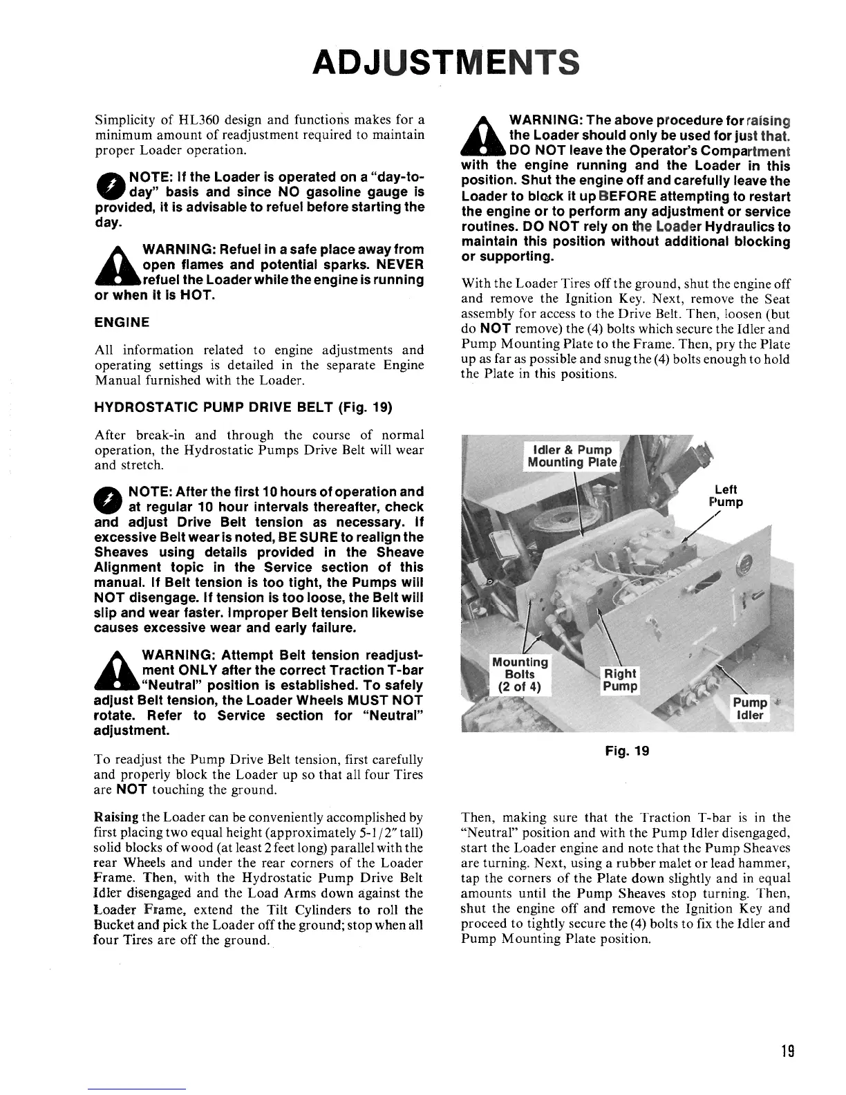
HYDROSTATIC
PUMP
DRIVE BELT (Fig. 19)
After break-in and through the course
of
normal
operation, the Hydrostatic
Pumps
Drive Belt will wear
and stretch .
NOTE: After the first 10 hours of operation and
•
at regular 10 hour intervals thereafter, check
and adjust Drive Belt tension
as
necessary.
If
excessive Belt wear
is
noted,
BE
SU
RE
to
realign the
Sheaves using details provided
in
the Sheave
Alignment topic
in
the Service section of this
manual. If Belt tension
is
too tight, the Pumps will
NOT
disengage. If tension
is
too loose, the Belt will
slip and wear faster. I mproper Belt tension likewise
causes excessive wear and early failure.
A
WARNING: Attempt Belt tension readjust-
ment ONLY after the correct Traction T -bar
"Neutral" position
is
established.
To
safely
adjust Belt tension, the Loader Wheels
MUST
NOT
rotate. Refer to Service section for "Neutral"
adjustment.
To readjust the
Pump
Drive Belt tension, first carefully
and properly block the Loader up so
that
all
four
Tires
are
NOT
touching the ground.
Raising the Loader can
be
conveniently accomplished by
first placing two equal height (approximately
5-1
/
2"
tall)
solid blocks
of
wood (at least 2 feet long) parallel with the
rear Wheels and under the rear corners
of
the Loader
Frame
. Then, with the Hydrostatic
Pump
Drive Belt
Idler disengaged
and
the
Load
Arms down against the
Loader
Fr
ame, extend the Tilt Cylinders to roll the
Bucket and pick the Loader off the ground; stop when all
four
Tires are off the ground.
with the engine running and the Loader
in
this
position. Shut the engine off and carefully leave the
Loader to block it up BEFORE attempting
to
restart
the engine or to perform any adjustment or service
routines. DO
NOT
rely on the Loader Hydraulics to
maintain this position without additional blocking
or supporting.
With the Loader Tires off the ground, shut the engine off
and remove the Ignition Key. Next, remove the Seat
assembly for access to the Drive Belt. Then, loosen (but
do
NOT
remove) the (4) bolts which secure the Idler and
Pump
Mounting Plate to the
Frame
. Then, pry the Plate
up as far as possible and snug the
(4)
bolts enough to hold
the Plate in this positions.
Fig. 19
Then, making sure
that
the Traction T-bar
is
in the
"Neutral" position
and
with the
Pump
Idler disengaged,
start the Loader engine and note
that
the
Pump
Sheaves
are turning. Next, using a rubber malet
or
lead hammer,
tap the corners
of
the Plate down slightly and in equal
amounts until the
Pump
Sheaves stop turning. Then,
shut
the engine off and remove the Ignition Key and
proceed to tightly secure the (4) bolts to fix the Idler and
Pump
Mounting Plate position.
19
 Loading...