NOTE:
BE SURE
thatthejumperbattery
is also
. a 12 volt battery.
•
1.
Turn
off both ignition keys before making
jumper
cable connections.
2.
Make sure
that
both vehicles are in neutral
and
NOT
touching each other.
3.
Remove the Filler Caps from
both
batteries
and
check and replenish the Electrolyte levels before
proceeding.
4.
Place a clean cloth over the uncapped Vent Holes
of
both
batteries
to
prevent boil-over and acid splash.
A
WARNING: If acid contacts your skin, eyes
or clothing, flush the area immediately with
large amounts of water.
5.
Interconnect the positive terminals (+)
of
both
batteries with one
jumper
cable.
6.
Interconnect the negative terminal
of
the booster
battery to
an
unpainted portion
of
the
Loader
Frame
or
engine block.
NOTE:
Twist the jumper cable clamps a couple
•
of times to make a good electrical contact.
DO
NOT
short the jumper cables or cross them.
The
negative
(-)
jumper cable connection should
NOT
be made directly to the Loader Battery to insure that
potential sparks are kept well away from the open
Filler Caps on the discharged Battery which will
tend to produce hydrogen gas.
7.
Proceed to start the Loader.
If
it does
NOT
start im-
mediately, start the engine
of
the booster vehicle to
avoid excessive drain on the booster battery.
8.
After the Loader
is
started
and
running smoothly,
remove the
jumper
cable from the Loader
Frame
member first. Then, detach the opposite end from
the booster battery. Then, remove the other
jumper
cable from the booster battery and the Loader
positive
(+) Terminal. .
Allow the Loader
to
recharge the Battery for approxi-
mately
10
minutes before attempting to operate the
Loader.
BE SURE
to
discard the cloths and replace the
Vent Caps on both batteries .
NOTE:
If Loader Battery discharging becomes
•
a reoccurring problem, have Battery checked
for possible dead cell
and/or
troubleshoot Electrical
System for possible shorted wire or damaged
insulation.
Recharging Weak Battery
If
Loader Battery becomes run-down
and
weak, it may be
desirable
to
recharge it with a plug-in 120 volt
AC
battery
charger unit. Follow operating instructions given with re-
charger unit and exercise all prescribed precautions.
BE
SURE
also to remove the
Loader
Battery Vent Caps
and
cover the uncapped Vent Holes and check the Electrolyte
level before starting the charger.
A
WARNING:
DO
NOT
attempt to recharge a
frozen Battery; this may cause it to rupture
or explode.
DO
NOT
attempt to recharge the
Battery in an area of sparks or near
an
open flame.
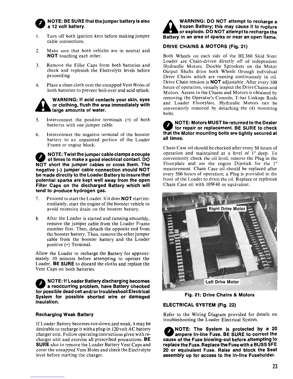
DRIVE
CHAINS
&
MOTORS
(Fig. 21)
Both Wheels
on
each side
of
the HL360 Skid Steer
Loader are Chain-driven directly off
of
independent
Hydraulic Motors. Double Sprockets on the
Motor
Output
Shafts drive
both
Wheels through individual
Drive Chains which are running continuously in oil.
Drive Chain tension
is
NOT
adjustable. After every
100
hours
of
operation, visually inspect the Drive Chains and
Motors. Access
to
the Chains and Motors
is
obtained by
removing the Operator's Console, T-bar Linkage Rods
and
Loader Floorplate. Hydraulic Motors can be
conveniently removed by detaching the (4) mounting
bolts.
NOTE:
Motors
MUST
be returned to the Dealer
•
for repair or replacement. BE SURE to check
that
the
Motor
mounting bolts are tightly secured at
all times.
Chain Case oil should be checked after every 50 hours
of
operation and maintained at a level
of
1"
deep.
To
conveniently check the oil level, remove the Plug in the
Floorplate and use the engine · Dipstick for the
1"
measurement. Chain Case oil should be replaced after
every 500 hours
of
operation; a Plug
is
provided in the
front
of
the Loader to drain the oil. Replace
or
replenish
Chain Case oil with lOW40 or equivalent.
Fig. 21: Drive Chains & Motors
ELECTRICAL
SYSTEM (Fig. 22)
Refer to the Wiring Diagram provided for details on
troubleshooting the Loader Electrical System.
NOTE:
The
System
is
protected
by
a 20
•
ampere In-line Fuse. BE SURE to correct the
cause of the Fuse blowing-out before attempting to
replace the Fuse. Replace the Fuse with a BUSS SFE
20 or equivalent Fuse. Raise and block the Seat
assembly up for access to the In-line Fuseholder.
23

 Loading...