Ignition Switch
Brown
(Back Side)
<+)
"'"
'C
12 Volt
a:
CP
/Battery
+-
Coil
20
Ampere
In-line Fuse
Solenoid
IIII
~I
Rectifier
Points
Hourmeter
Starter
Box
Engine
Alternator -
Stator
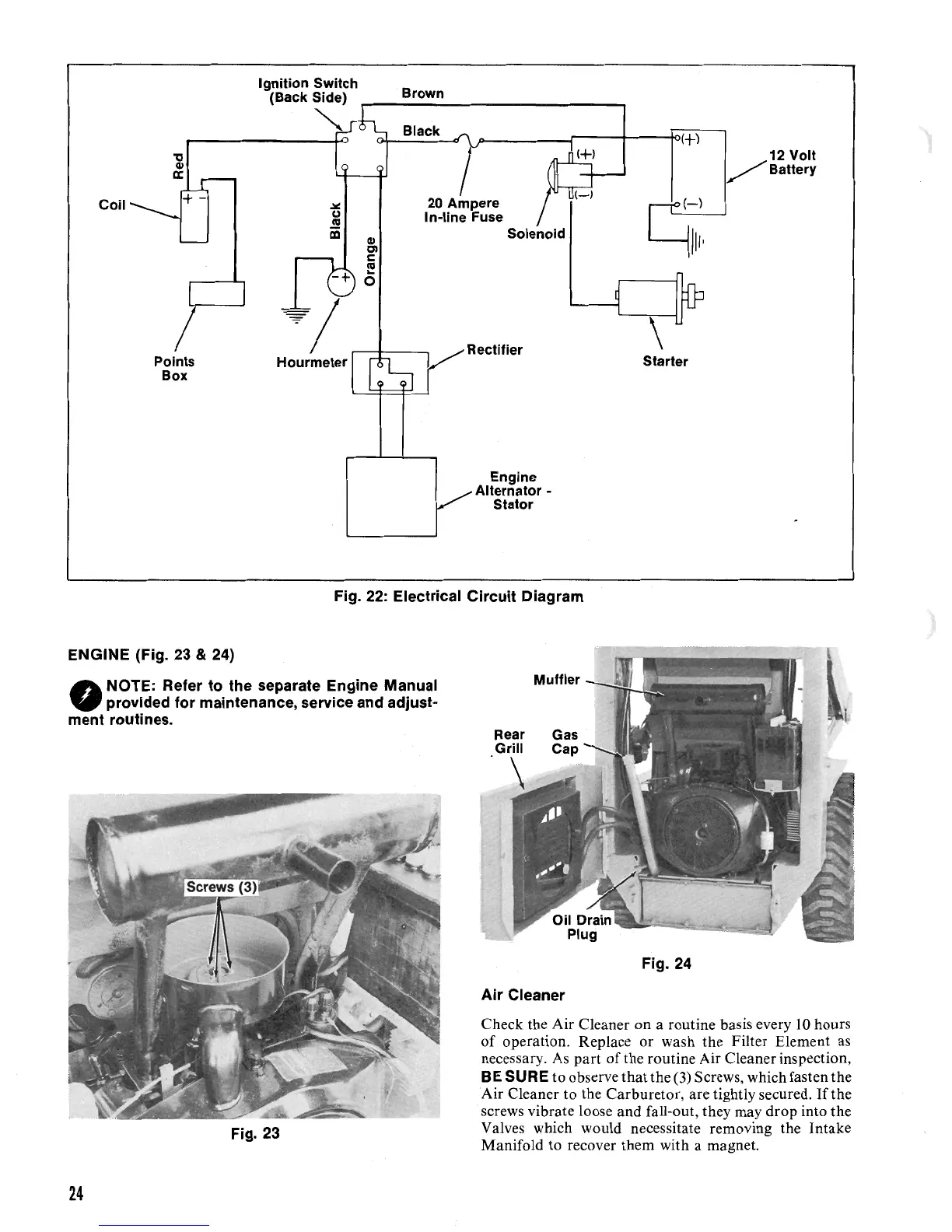
Fig.
22:
Electrical Circuit Diagram
ENGINE (Fig. 23
& 24)
NOTE: Refer
to
the separate Engine Manual
•
provided for maintenance, service and adjust-
ment routines.
Fig. 24
Air Cleaner
Check the Air Cleaner on a routine basis every
10
hours
of
operation. Replace or wash the Filter Element as
necessary.
As
part
of
the routine Air Cleaner inspection,
BE
SURE to observe
that
the
(3)
Screws, which fasten the
Air Cleaner
to
the
Carburetor
, are tightly secured.
If
the
screws vibrate loose and fall-out, they may drop into the
Valves which would necessitate removing the Intake
Fig. 23
Manifold to recover them with a magnet.
24

 Loading...