EasyManua.ls Logo

GEM Equinox Pro - User Manual

GEM Equinox Pro
17 pages
Print Icon
To Next Page IconTo Next Page
Loading...
1 1
1 1
1
JJ
JJ
J
Index
Soldering point.
Male connector.
Female connector.
M/F faston connector.
Test point.
Supply voltage. Logic supply ground.
Analog supply ground.
Chassis ground.
Earth ground.
Flag joined with one or more flags
GENERALMUSIC S.p.A. Sales Division: 47842 S.Giovanni in Marignano (RN) ITALY - Via delle Rose, 12
Phone 0541/959511 - Fax 0541/957404 - GENERALMUSIC on the NET: http://www.generalmusic.com
Opening & Keyboard Disassembling Instructions2
Layout3
Assembly
5
6 Supply, Mixer, Analog I/O and Controls & Midi I/O Schematics, Adjustment Table
7
Block Diagram and Test Procedure & Adjustments
8 Keyboard L & R Contacts and Interface Schematics
9
Cpu & Sound Generator Schematic (Part 1/2)
10
Cpu & Sound Generator Schematic (Part 2/2)
11
Vocal Processor Schematic & Pcb Layout
12
Supply, Mixer, Analog I/O and Controls & Midi I/O Pcb Layouts
13
Spare Part List
14
Timings Table
Controls Panel and Interface Schematics
Controls Panel and Interface Pcb Layouts
4
Cpu & Sound Generator Map
Cpu & Sound Generator Pcb Layout
15
16
17
SERVICE MANUAL
CODE: 270234
Warnings
with the same signal name inscribed.
Address
ATTENTION
Observe
precautions when handling electrostatic sensitive devices.
Notice
Service must be carried out by qualified personnel only. Any tampering carried out by unqualified personnel during the guarantee period
will forfeit the right to guarantee.
For a correct operation of the instrument, after having switched off, be careful to wait at least 3 seconds before switching on again.
To improve the device's specifications, the schematic diagrams may be subject to change without prior notice.
All components marked by this symbol have special safety characteristics, when replacing any of these components use only
manufacturer's specified parts.
The (µ) micro symbol of capacitance value is substituted by U.
The (
) omega symbol of resistance value is substituted by E.
The electrolytic capacitors are 25Vdc rated voltage unless otherwise specified.
All resistors are 1/8W unless otherwise specified.
All switches shown in the "OFF" position. All DC voltages measured to ground with a voltmeter 20KOhm/V.
Question and Answer IconNeed help?

Do you have a question about the GEM Equinox Pro and is the answer not in the manual?

Summary

General Safety and Handling

General Safety Notice

General safety instructions for qualified personnel and service procedures.

Electrostatic Discharge (ESD) Precautions

Observe precautions when handling electrostatic sensitive devices.

Company Address

Opening and Keyboard Disassembly

Opening Instructions

Steps for opening the instrument and removing the chassis.

Keyboard Separation

Procedure for separating the keyboard from the chassis.

Keyboard Disassembling Instructions

Steps to remove key return springs and unlock keys.

Test Procedures and Adjustments

Test Instruments and Accessories

Required instruments and accessories for testing procedures.

Setup and Initial Checks

Procedures for setting up the instrument and performing initial checks.

System and Component Checks

Detailed checks for Aftertouch, MIDI, RS232, Inputs, DSP, Vocal Processor, Noise level, Data Hold, and Panel Key/LEDs.

Memory and Option Checks

Procedures for verifying memory modules and optional accessories.

Schematic Diagrams and Adjustments

Adjustment Table

Table detailing adjustments for Aftertouch and Pitch Centre.

Keyboard and Computer Connections

Keyboard Interface and Contacts Boards

PCB layouts for keyboard interface and contact boards.

Computer Interface Connections

Details on RS422 and RS232 connections for computer interfaces.

Timing Diagrams

System Timing

Timing diagrams for power, display, LCD, and data bus operations.

Disk Drive Timings

Timing diagrams for floppy and hard disk drives.

Controls and Interface Schematics

Controls Panel Board Schematic

Schematic for the controls panel board with various controls.

Controls Interface Board Schematic

Schematic for the controls interface board.

Controls and Interface PCB Layouts

Controls Panel Board Layout

Reverse layout of the controls panel board.

Controls Interface Board Layout

PCB layout for the controls interface board.

Keyboard Interface Board Layout

PCB layout for the keyboard interface board.

CPU & Sound Generator Board Schematic (Part 1;2)

DRAM Module and CPU Connections

Schematic details for DRAM modules and CPU connections.

FPGA and Memory Interfaces

Schematic details for FPGA, static RAM, and vocal processor interfaces.

CPU & Sound Generator Board Schematic (Part 2;2)

Disk and SCSI Interfaces

Schematic for floppy, hard disk, and SCSI interfaces.

Buffer and Sample Memory Modules

Schematic details for buffer modules, sample DRAM, and DRAM modules.

CPU & Sound Generator Board PCB Layout

Component Placement Diagram

PCB layout showing component placement for the CPU & Sound Generator Board.

CPU & Sound Generator Board User Map

Board Connections and Jumpers

Diagram showing board connections, jumper settings, and expansion options.

Expansion Module Information

Details on Sample DRAM, SCSI, and Hard Disk expansion modules.

Vocal Processor Board

Vocal Processor Schematic

Schematic diagram of the Vocal Processor Board.

Vocal Processor PCB Layout

PCB layout of the Vocal Processor Board.

Overview

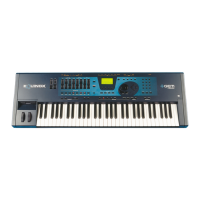
This document serves as a service manual for the EQUINOX PRO device, offering comprehensive information for its maintenance, repair, and understanding.

Function Description

The EQUINOX PRO is a sophisticated electronic musical instrument, likely a synthesizer or workstation, designed for sound generation, manipulation, and performance. Its architecture suggests a complex interplay of digital and analog components for sound synthesis, effects processing, and user interaction. Key functional blocks include:

  • CPU & Sound Generator Board: This is the core processing unit, responsible for overall system control, sound synthesis, and managing various peripherals. It integrates a Motorola MC68360 CPU, FPGA for LCD mode, static RAM, and flash memory for storing operating system and sound data. It also interfaces with DRAM modules for sample storage and a Digital Sound Processor (DSP) for advanced audio processing.
  • Mixer Board: Handles audio signal routing, mixing, and basic signal conditioning. It includes buffers, filters, and muting circuits for managing multiple audio inputs and outputs.
  • Analog I/O Board: Manages the analog audio inputs and outputs, including gain control for inputs and buffering for outputs. It provides the interface between the digital sound generation and the analog world of audio signals.
  • Controls Panel Board & Interface Board: These boards manage user input from various controls such as buttons, potentiometers, and wheels. The interface board translates these physical inputs into digital signals for the CPU.
  • Keyboard Interface Board: Dedicated to processing input from the keyboard contacts, translating key presses and releases into digital data for the CPU.
  • Vocal Processor Board (Optional): An optional accessory designed for processing vocal signals, likely including effects like vocoding, harmony generation, or pitch correction. It integrates an ADSP2181 Digital Signal Processor.
  • Power Supply Unit: A switching power supply unit providing the necessary DC voltages for all internal components.
  • Storage Devices: Includes a floppy disk drive and support for a hard disk drive (optional) and SCSI interface for external storage.
  • Display: Features an LCD display (128x64 dots) for user feedback and menu navigation.
  • Connectivity: Offers MIDI I/O (In, Out, Thru) for communication with other musical instruments, RS232 and RS422 ports for computer connectivity, and various audio inputs and outputs.

Important Technical Specifications

  • CPU: Motorola MC68360
  • Memory:
    • Flash Memory: 16Mbit (likely for OS and core sounds)
    • Static RAM: 256Kbit (for LCD mode)
    • Dynamic RAM (DRAM): Supports 16Mbit modules, with expansion slots for SIMM DRAM modules (1Mbyte or 4Mbyte x8/x9, 30-pin, 70nS max access time). The CPU board supports 2Mbyte or 8Mbyte sample DRAM expansion.
  • Digital Sound Processor (DSP): ADSP2181 (on Vocal Processor Board)
  • Display: 128x64 dots LCD
  • Power Supply: 100-230Vac Switching Supply Unit (SNP9541 40W)
  • Connectivity:
    • MIDI: In, Out, Thru (A and B)
    • Serial Ports: RS232 (Computer), RS422 (Apple Macintosh)
    • SCSI Interface
    • Floppy Disk Drive: 3.5"
    • Hard Disk Drive: Optional
    • Audio Outputs: Multiple analog outputs (OUT-1, OUT-2, OUT-L, OUT-R, PHONES)
    • Audio Inputs: Analog inputs (INPUT-1, INPUT-2, MIC/LINE)
  • Keyboard: Supports 61, 76, or 88 keys with contact boards and an aftertouch mechanism.
  • Clock Frequencies: 32768 Hz (quartz), 4.19 MHz (quartz), 20MHz (ceramic reson.), 45.1 MHz (quartz for DSP).

Usage Features

The EQUINOX PRO is designed for comprehensive musical production and performance.

  • Sound Generation: Utilizes a CPU and dedicated DSP for advanced sound synthesis and effects. The presence of large sample DRAM modules indicates extensive sample playback capabilities.
  • User Interface: Features a controls panel with numerous buttons, potentiometers, and a display for intuitive parameter adjustment and navigation. Pitch bend and modulation wheels offer expressive control.
  • Keyboard: A velocity-sensitive keyboard with aftertouch provides expressive playing capabilities.
  • Storage: Internal flash memory for core data, expandable DRAM for samples, and support for floppy and hard disk drives allow for extensive sound libraries and project storage.
  • Connectivity: MIDI allows integration into a larger studio setup. Computer interfaces (RS232/RS422) enable software control, data transfer, and potentially external sequencing.
  • Vocal Processing (Optional): The optional vocal processor enhances the instrument's capabilities for vocalists or producers working with vocal tracks, offering real-time effects and manipulation.
  • Audio Routing: Multiple audio inputs and outputs provide flexibility for connecting external audio sources and routing the instrument's sound to various destinations.

Maintenance Features

The service manual provides detailed instructions and diagrams for maintaining and repairing the EQUINOX PRO.

  • Disassembly Instructions: Clear steps for opening the chassis and separating the keyboard, including screw locations and precautions.
  • Test Procedure & Adjustment: A comprehensive guide for checking instrument operations and making adjustments. This includes:
    • Aftertouch Adjustment: Using a VR1 trimmer on the CPU board to calibrate aftertouch response.
    • MIDI, RS232, RS422 Mode Tests: Verifying communication protocols.
    • Panel Key and LED Test: Checking the functionality of all panel buttons and LEDs.
    • Pitch Bend and Modulation Wheels Adjustment: Calibrating the range and center position of the wheels.
    • Memories and Optional Accessories Test: Verifying the functionality of SIMM modules, sample DRAM, disk drives, SCSI interface, and hard disk.
    • Inputs, DSP, and Vocal Processor Test: Checking audio signal paths and DSP functionality.
    • Noise Level Check: Ensuring acceptable audio noise levels.
    • Data Hold Test: Verifying data integrity and storage.
    • Final Check & Reliability Check: Comprehensive operational tests and a "shake test" to identify loose connections or intermittent faults before delivery.
  • Schematic Diagrams: Detailed electrical diagrams for all major boards (CPU, Mixer, I/O, Controls, Keyboard Interface, Vocal Processor, Power Supply) to aid in troubleshooting and component replacement.
  • Pcb Layouts: Physical layouts of the printed circuit boards, showing component placement and traces.
  • Timings Table: Provides critical timing diagrams for power on/off, reset, LCD, floppy disk, hard disk, and PCM serial data bus, essential for diagnosing timing-related issues.
  • Spare Part List: A comprehensive list of all components, including part numbers, descriptions, and quantities, facilitating easy ordering and replacement.
  • Safety Precautions: Warnings regarding service by qualified personnel, waiting periods after power cycling, special safety characteristics of certain components, and precautions for handling electrostatic sensitive devices.
  • Component Specifications: Notes on capacitance and resistance value symbols, electrolytic capacitor voltage ratings, and resistor wattage.

GEM Equinox Pro Specifications

General IconGeneral
BrandGEM
ModelEquinox Pro
CategoryElectronic Keyboard
LanguageEnglish

Related product manuals