Getting Started with Cinterion
®
PLS62-W
3 Appendix: DSB75 Adapter
16
PLS62-W_startup_guide_v01 2018-05-17
Confidential / Released
Page 13 of 17
3 Appendix: DSB75 Adapter
The PLS62-W Evaluation Module connects to the 80-pin board-to-board connector X120 on
top of the DSB75 Adapter. The 2x40-pin header X101/X102 of the DSB75 Support Board con-
nects to the 80-pin female connector X135 located on the back of the DSB75 Adapter.
By default, when shipped from factory, all jumpers on the DSB75 Adapter are set for use with
PLS62-W, even though not all of them are required - see Figure 7.
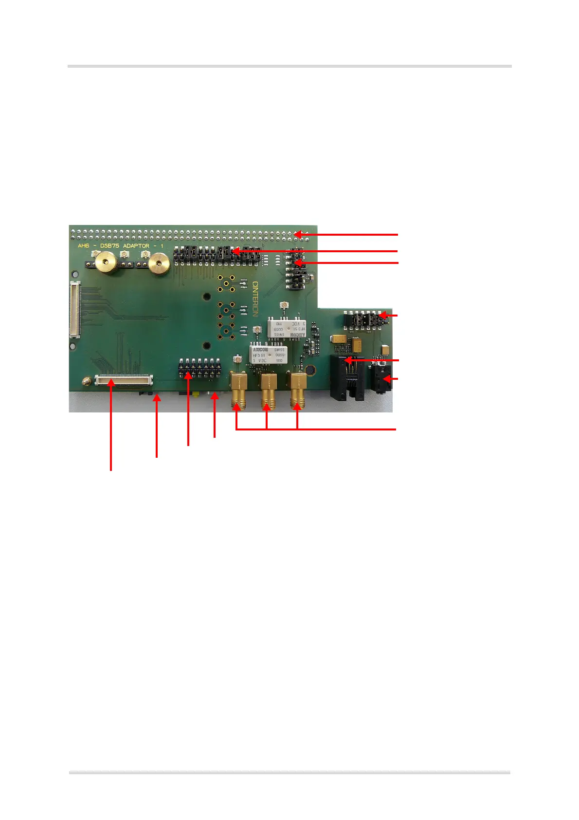
The adapter is illustrated in Figure 6 and Figure 7.
Figure 6: DSB75 Adapter with default jumper positions
X135 (test points on top
and connector on bottom)
X308/X309
X305
X311
Handset jack X310
TTY jack X307
SMA antenna connectors
X390, X351, X353
USB 2.0 Mini-B5 connector X306
SIM interface X171
SIM card reader X170
80-pin board-to-board connector X120
X350
X352
X391

 Loading...