;ratulations
on purchasing
the
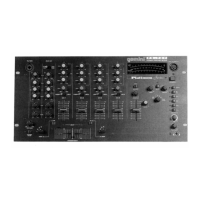
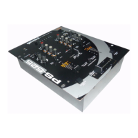
Gemini PS-525 PRO mixer. This
state
of
.R
mixer includes the latest features and
is
backed
by a three year
:d
warranty, excluding crossfader and channel slides. Prior to
use,
uggest that
you
carefully
read all the instructions.
:ut
Feature for Bass, Mid and High for
each
channel
1
Stereo channels
1
Phono/Line
Convertible, 2 Line and
1
Mit
input
1!4”
DJ
Mit
jack
-OW,
Mid, High, Gain and Balance controls on
each
channel
Dunch
In for
each
channel
Qlaster
Output, Booth and
Record
Outputs
.3ual
mode display
All
operating instructions should be read before using this equipment.
To reduce
the
risk
of
electrical
shock,
do not open the unit. There are
NO USER REPLACEABLE PARTS INSIDE. Please refer servicing to a
qualified
Service
technician.
/
In
the
U.S.A.,
if
you
have
any
Problems
with
this
uni
cal1
1-800-476-8633
for
customer
Service.
DO
not
return
equipment
to
your
dealer.
DO
not
expose this
unit
to
direct
sunlight
or
to a heat
Source
such
as
a
radiator
or
Stove.
This unit should be cleaned only with a damp
cloth.
Avoid
solvents
or
other
cleaning
detergents.
When moving this equipment, it should be
placed
in
its
original
carton
and
packaging.
This will reduce the risk of darnage
during
transit.
DO NOT EXPOSETHIS UNITTO RAIN OR MOISTURE.
DO NOT USE ANY SPRAY CLEANER OR LUBRICANT ON ANY
CONTROLS OR SWITCHES.
Before plugging in the power
cord,
make sure that the VOLTAGE
SELECTOR (27)
switch
is
set
to
the
correct voltage.
IOTE:
This
product
is
double
insulated
and
not
intended
,i
be
grounded.
Make
sure
that the POWER (21)
switch
is in
the
off Position.
The PS-525 PRO
is
supplied with 3 sets of amp output
jacks.
The
MASTER OUTPUT (28)
jacks
are
unbalanced
and used
to
connect to
your main amplifier. The OUTPUT REC (30)
jacks
tan
be used
to
connect the mixer
to
the
record
input of your
recorder
enabling you
to
record
your mix. The OUTPUT BOOTH (29)
jacks
allow
you
to
hook up
an additional amplifier.
The DJ
MIC
(1) input (found on
the
front
Panel)
accepts a 114”
connector and
balanced
and
unbalanced
microphones.
i
-.
On
the
rear
Panel
are 2 stereo
PHONOILINE
(33, 35) inputs and 2
stereo
LINE
(32,34)
inputs. The
PHONONLINE
SWITCHES
(36,37)
enable you
to
set
the
(33, 35) inputs
to
Phono
or
Line. The phono
inputs
will
accept
only
turntables
with a
magnetic
cartridge. A
GROUND SCREW (38) for you
to
ground your
turntables
is
located
on
the
rear
Panel.
The stereo
line
inputs will
accept
any line
level
input
such
as
a CD
player,
a
cassette
player,
etc.
6.
Headphones
tan
be plugged into the front
Panel
mounted
HEADPHONE
(22)
jack.
Depending
on
your
System
configuration,
sometimes applying the ground
will
create
a quieter
Signal
path. Sometimes lifting
the
ground
tan
eliminate
ground loops and hum
to
create
a quieter
Signal
path.
1. With the mixer on, listen to
the
System
in idle mode (no
Signal
present)
with
the
ground applied (the GROUND LIFT SWITCH (31) in
the
left
Position).
2. Then turn the power off before moving the GROUND LIFT
SWITCH (31). Lift
the
ground by moving the GROUND LIFT SWITCH
to
the
right,
turn
the
power back
on
and listen to detenine
which
Position
will provide a
Signal
devoid of
background
noise and hum.
Keep the GROUND LIFT SWITCH in
the
ground
Position
if
the
noise
level
remains
the
same in either Position.
CAUTION: DO NOT TERMINATE THE AC GROUND ON THE POWER MIXER
IN ANY WAY. TERMINATION OF THE AC GROUND CAN BE HAZ4RDOUS.
POWER ON:
Once
you
have made all
the
equipment connections
to
your mixer, press the POWER SWITCH (21).
CHANNEL 1: The GAIN
(8),
HIGH
(9),
MID
(lO),
and LOW (11) controls
allow
you to
fully
adjust
the selected
source.
Switch
#
(12)
allows
you
to
select either
the
PHON0
l/LINE
1 (35) or
the
LINE
2 (34) input. The
CHANNEL
SLIDE
(13) controls the output
level
of this channel.
CHANNEL 2: The GAIN
(8),
HIGH
(9),
MID
(IO),
and LOW (11) controls
allow
you
to
fully
adjust
the
selected
Source.
Switch
#
(19)
allows
you
to select either the PHON0
21LINE
3 (33)
or
the
LINE
4 (32) input. The
CHANNEL
SLIDE
(20) controls the output
level
of
this
channel.
NOTE:
There
is
Low,
Mid
and
High
equalization
for
each
channel
with
an
extremely
wide
range
of
adjustment.
SUGGESTION:
You
tan
use
the Cut Features on
each
channel
to
remove Low, Mid
and/or
High to
create
special
effects.
4.
CROSSFADER SECTION: The CROSSFADER (18) allows the mixing of
one
Source
into another. The
left
side of the CROSSFADER (18)
is
CHANNEL 1 and the right side
is
CHANNEL 2. The CROSSFADER
REVERSE SWITCH (17)
allows
you to reverse the crossfader so
that
CHANNEL 2
is
controlled
by the
left
side of the crossfader and
CHANNEL 1
is
controlled
by the right side of
the
crossfader.
NOTE:
When
the
CROSSFADER
REVERSE
SWITCH
(17)
is
activated
(moved
to
the
right),
only
the
crossfader
reverses.
The
Channel
Slides,
Punch
In,
Gain,
and
tonal
controls
da
not
reverse.
The CROSSFADER (18) in your
unit
is
removable and if
the
need
arises
tan
be easily replaced. Crossfader
units
are available in three
varieties. Part
#
RF-45
(which
is
identical
to
the
crossfader supplied
with the mixer) has a 45 mm travel from side
to
side. Part
#
RF-30
is
available with a 30 mm
travel
distance. Also available
is
the PSF-45
with a
special
curve
designed for scratch mixing. Just
purchase
one
of these crossfader units from your Gemini
dealer
and follow
these
instructions:
Page 3
 Loading...