- Mounting Diagrams -
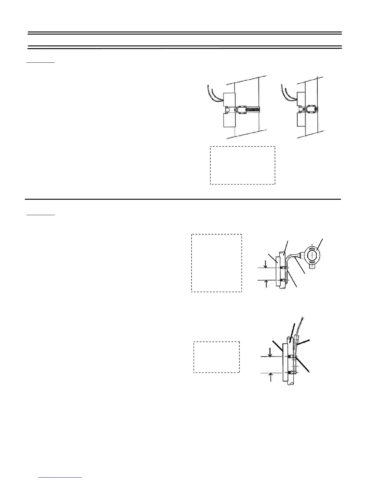
Diagram A
Position the switch module 180° from
the flag assembly and within indicating range.
2. Slide the switch clamp between the flag assembly
and the weldment of your SureSite Magnetic Level
Indicator.
3. With the switch module located at the desired fluid
level, tighten the clamp screw securely; not to exceed
a torque of 10 lb-inches.
4. Connect the switch module leads to the load circuit.
Diagram B
Position the switch module 180° from
the flag assembly and within indicating range.
2. Slide the tabs of the switch clamps between the
flag assembly and the weldment of the Mini
SureSite Magnetic Level Indicator; wrapping
the retaining screw-end around the upper and
lower stem of the switch, as shown.
3. With the switch module located at the desired fluid
level, tighten the clamp screw securely; not to exceed
a torque of 120 lb-inches.
4. Connect the switch module leads to the load circuit.
Standard SureSite
®
Switch
Part Numbers
83100, 83110,
83120, 83130,
83140, 83150,
84320, 84330
Switch
Part Numbers
83150, 84320
Mini SureSite
®
J-Box Not
Included
On Type
83140
1-1/4”
O.D.
Tubing
Flag
Assembly
2-1/2”
Ref.
Switch
Module
#24 Clamp
(P/N 85576)
-2 Required
1-1/4”
O.D.
Tubing
Flag
Assembly
2-1/2”
Ref.
Switch
Module
#24 Clamp
(P/N 85576)
-2 Required
Switch
Part Numbers
80469, 85350, 86435,
86567, 87480
 Loading...