21
1. 产品介绍 Product Introduction
控制系统由控制器和电机两部分组成:
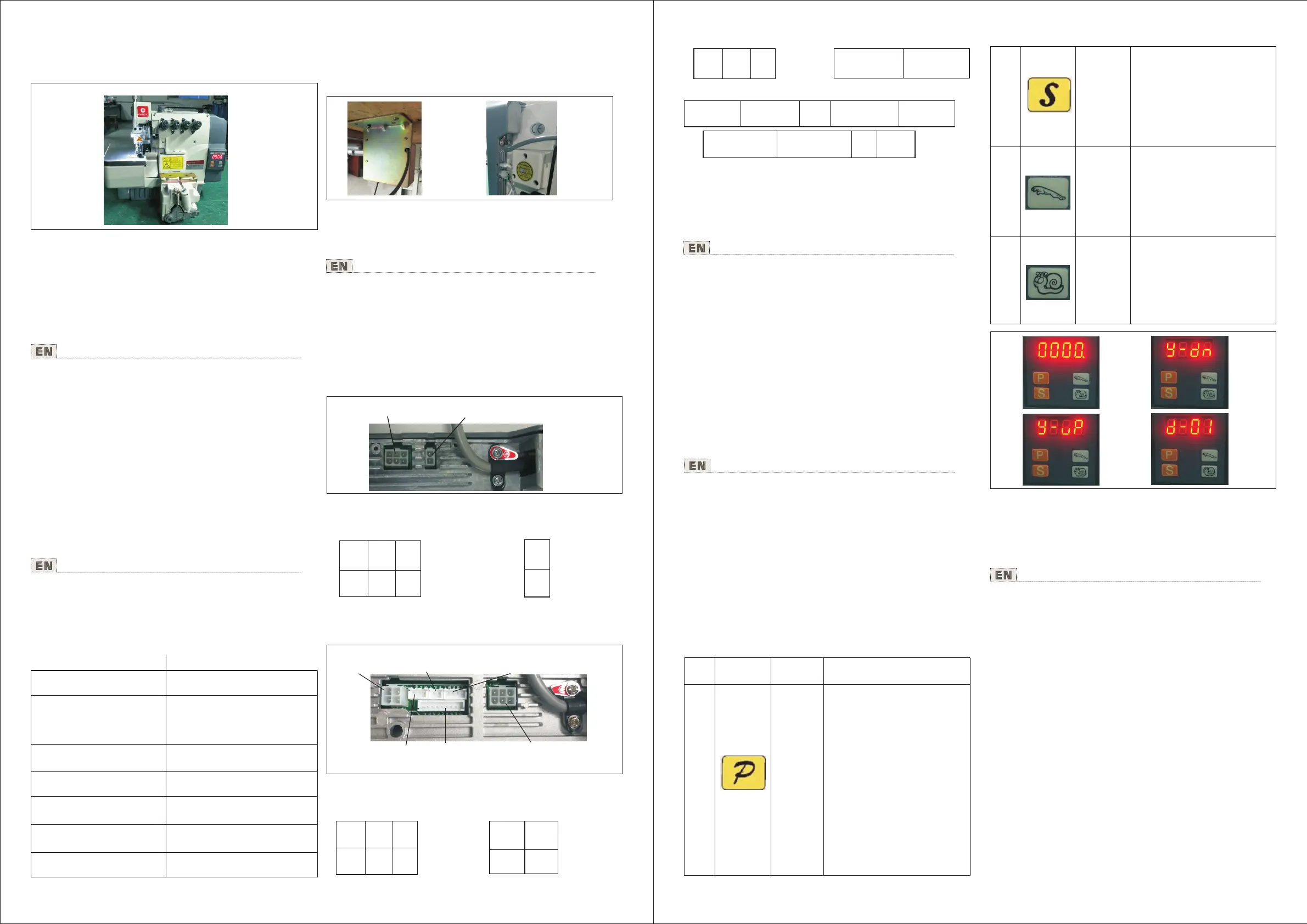
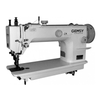
控制器 : 控制器包括调速器,见图1
1).组成 Component
The system is made of controller and motor.
Controller: The controller is made of speed governor and
control box (as picture 1)
图1
一体系统适用于包缝机设备配套使用。
安装拆卸任何组件时必须先断开电源﹗
2).系统配套适用机型范围 Application
Organic whole system is applicable to overlock. Interlock sew-
ing machine and those machine load light.
The electric power must be cut off in case of installation or
dismantlement!
2. 一体式系统 的安装 Installation And
Adjustment Of Organic Whole System
本控制器主芯片采用美国爱特梅尔公司最新的AVR单片
机,该单片机有着丰富的片内资源,通过优化算法编制
的软件,精确控制电机的工作状态。电机的功率驱动采
用6个晶体管“IGBT”,该晶体管具有完善的过压、过流、
过热等自动保护功能。整个控制器结构十分精练且性能
优异。脚踏调速器为电机速度控制部件。
The chip of this controller is applied by the latest AVR SCM
of ATMEL LIMITED , which can control the motor accurately
with optimization algorithm. The power driver of the motor
has six transistors “IGBT”. This has perfect
performance on the protection to overvoltage, over current
and overheating. The instruction of controller is perfect and
efficient. Pedal-driven speed governor is a part of motor
speed control.
transistors
最大扭矩
Maximum torque
电机转速(出厂设置)
Speed
上下停针
Needle up/down
过载保护
Transistor protection
有
Yes
2.5N.m
5000
r/min
有
Yes
2).系统接线(见图4)(E专用)
Connection of system (as picture 4)(Special E Model)
图4
将控制器电源线接入规定的供电系统,用户供电系统必
须有独立的接地装置,控制器箱体必须可靠接地!将调
速器的各个插头,平稳插入机器尾部对应的插座即可
,插好后,请再检查一下插头插座接触是否牢靠,调整
塑料护套的位置,使塑料护套完全包裹住插头。
Connect controller power supply wire into the regulation of
power system, which should have separately earth device,
and the control box must be connected to earth safely. Ins-
ert the speed controller into the socket behind the . When
everything is ready, check it if the connection stable again,
and then adjust the position of plastic sheath in order to c-
over the plugs totally.
4).调试 Adjustment
针位的调整
接通电源,打开控制器电源开关,用手转动缝纫机手轮,
在上针位时,松开和移动有红色标记的磁钢位置,使同
步器上的红色发光管点亮,然后再拧紧磁钢固定螺钉,
同理,用手转动缝纫机主动轮,在下针位时,松开和移
动无标记的磁钢,使同步器上的绿色发光管点亮,然后
拧紧磁钢固定螺钉,至此同步器的针位信号已调整好。
Adjustment of needle position :
Connect to the power, and turn on the mains switch of control
box. Rotate the driver wheel of sewing machine, when it stop
at the up needle position, Loosen and moving the red mark
of alnico, lighten the red luminotron in the synchronizer, and
then fix the screw. In a similar way, Rotate the driver of
sewing machine, when it stop at the lower needle position,
Loosen and moving unmarked mark of alnico, lighten the
green luminotron in the synchronizer and then fix the screw.
So far, the synchronizer needle position signal has adjusted.
3. 设置使用 说明 Setting Procedures
图2 图3
1).脚踏开关的安装 Installation of controller
在台板右前下方,用Φ3钻头钻两个深20mm的孔,孔距
195mm,然后用随机附带的木螺钉,将控制箱固定拧紧,
将调速器、同步器的插头正确插入相应的插座,并将电
缆线扎好,固定在远离皮带位置的台板下。见图2 图3
hand front bottom of table, the distance between them is
195mm,and then fix the control box tightly with wooden
screw. Insert the plug of motor, synchronizer and speed
controller into relevant socket, and then fix the packed cable
conductor to the table which far away from belt. (as picture
2 and 3)
Cutting two holes of 20 mm deep with a Φ3 drill in the right
序号
NO.
按键图标
BUTTON
按键名称
NAME
说明
DETAILS
1.按P键1秒,数 码管显示y-dn
是上下停 针功能。
2.按+数码管 显示y-up是 上停
针,单停 针功能。
3.按-数码管 显示y-dn是 下停
针、倒踩 踏板上停针 ,双停针
功能。
调节
针位键
Needle
position
button
(E专用)
(Special
E model)
1
1.Keep pressing P 1 second, the
LED display y-dn means up and
down needle position function.
2.Press+, the LED displaying
y-up is up needle position,single
needle position function.
3.Press-, the LED displaying
y-dn is down needle position,
reverse pedal up needle position,
double needle position function.
2
按此键加 速,在300-6000rpm
转速区域, 每按一次+100rpm。
在150-300转速区 域,每按一
次增加50rpm。
调节
转向键
1.按S键5秒,数 码管显示d-01
转向是顺 时针方向。
2.按+键,数 码管显示d-02在
转向是逆 时针方向。
3
加速键
减速键
按此键减 速, 在300-6000rpm
转速区域 ,每按一次- 100rpm。
在150-300转速区 域,每按一
次减少50rpm。
Accelerating
button
Press + to accelerate. In 300-6000
rpm speed area . Each press +100
rpm. In 150-300 speed area, each
press + 50rpm。
Direction
button
(E专用)
(Special
E model)
1.Keep Pressing S 5 seconds,
LED displaying d-01 is clockwise
direction.
2.Press+, LED display d-02 is
anticlockwise direction.
4
Press- to decelerate. In 300-6000
rpm speed area, Each press -100
rpm. In 150-300 speed area,each
press -50rpm。
Decelerating
button
图6 图7
1).操作面板使用 说明(客户菜 单)
Application description of operation panel (client menu)
图8 图9
①.开机显示为工作界面,数码管显示“0000” 图6
③.调节转向键:按S键5秒,数码管显示d-01转向是顺
时针方向图9。
②.调节针位键:按P键1秒,数码管显示y-dn是上下停
针功能。图7.图8
①.Boot display for work interface, digital tube display "0000",
(photo 6)
衣车 灯
插口
LED Light socket
调速 器线插口
Speed adjustor socket
前切 感应插口(九 芯)
Before sewing thread
cutter(9Pin)
信号
空
空
空
地
5V
Sig
N/A N/A
5V
N/A
GND
剪线+
JXB+
剪线-
JXB-
剪线+
JXB+
剪线-
JXB-
调速 器插口
Speedadjustor
socket
电磁 铁插口
Magnet socket
地
信号
电源
抬压脚接收+
GND
FT
5VT
抬压脚接收+
5VT TYS
安全 开关插口
Speed adjustor socket
抬压 脚电磁铁 插口
Magnet socket
前切接收+
前切接收- 电源 抬压脚发射-
后切发射-
BS FC-S 5VT TYL FL
...
...
开关剪线信号 开关剪线电源 空
LED灯-
BJS
5VT
N/A LP
前切感应插口 Safety sewing thread cutter socket
3).性能及指标参数 Performance And Parameter
电源供电电压
Power voltage range
(please confirm the
supply voltage)
输出功率
Motor output
AC 220V±10﹪
550W
包缝一体机
Overlock
机型
Model
AC 110V±10﹪ 50/60 Hz
AC 110V~220V
控制箱尾部接口定义(见图4)(E专用)
Connector definition behind of the control box(as picture4)
(special E model)
调速器线插口
信号
空 空
空
地
5V
Speed adjustor
wires connector
5V-
5V+
衣车灯插口
LED Light
connector
Sig
N/A N/A
5V
N/A
GND
5V-
5V+
电磁 铁插口(四芯)
Magnet socket
(4Pin)
抬压 脚电磁铁 插口(二芯 )
Foot-lifter socket
(2Pin)
后切 感应插口 (四芯)
After sewing thread
cutter socket(4Pin)
安全 开关插口 (三芯)
Safetyswitch socket
(3Pin)
调速 器插口(六芯)
Speed adjustor( 6Pin)
②.Needle position button: Keep pressing P 1 second, the
LED display y-dn means up and down needle position
function. (photo 7.photo 8)
③.Direction button: Keep Pressing S 5 seconds, LED
displaying d-01 is clockwise direction.(photo 9)
2).设置参数菜单(长按P键3秒进入)(E1/E2专用)
Setting Menu Press P for 3 second to enter (Special E1/E2
model)
①光电快速学习(S):
Electronic Sensor quick adjust
确认前后光电感应之间无遮挡,长按S键直到屏幕显示
SC表示学习成功;如显示FA,则表示学习失败,请检查
确认接插口等硬件没问题后重新检测学习。
Ensure there is no materials between all sensors, Pres-
s S till display SC to quick adjust the sensors. If displ-
ay FA, means the adjustment failed, check all the con-
nection and re-adjust.
②光电精确学习模式(P-15):
Electronic sensors precious adjust
长按P键进入P-00,按加速键到P-15;按S进入参数默认
显示0,按加速键到1,再按S进行无布学习(光电感应
控制箱尾部接口定义(见图5)(E1/E2专用)
Connector definition behind of the control box(as picture5)
(Special E1/E2 model)
3).系统接线(见图5)(E专用)
Connection of system (as picture 5)(Special E1/E2 Model)
图5