512, 514, 532
10 / 16
1 Assembly / disassembly
of gland packing for
GEMÜ 514, 532
Please refer to installation, operating and
maintenance instructions GEMÜ 514 and
GEMÜ 532 - chapter 11.1 "Installing the
valve" and chapter 20 "Sectional drawings
and spare parts".
1.1 Disassembly of actuator
and gasket 4
1. Move actuator A to the open position.
2. Loosen union nut a.
3. Remove actuator A from valve body 1.
4. Remove gasket 4.
+
Important:
After disassembly, clean all parts
of contamination (do not damage
parts). Check parts for potential
damage, replace if necessary (only
use genuine parts from GEMÜ).
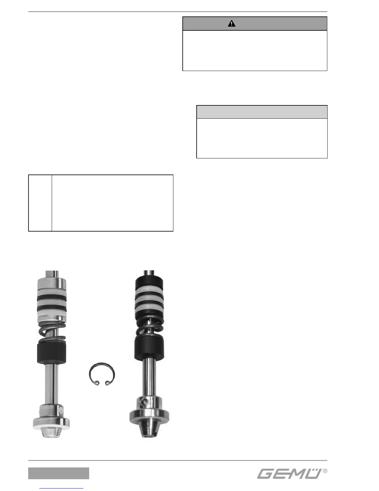
1.2 Replacement of the gland
packing
Brass version Stainless steel version
Support ring 7
Chevron packings:
8 PTFE - light
33 elastomer - dark
Pressure ring 9
Compression spring 6
Guide bush 5
}
}
Valve spindle 2
Circlip 3
WARNING
The actuator cover is under spring
pressure!
® Risk of severe injury or death!
G Only open the actuator under a press.
1. Disassemble actuator A as described in
chapter 1.1, points 1-4.
2. Clamp actuator A in a press.
CAUTION
Actuator cover will break if
pressure is too high!
® Only use minimum required
pressure.
3. Loosen and remove connecting screws
between cover and base of actuator A.
4. Slowly release the press allowing the
cover of actuator A to raise under the
relaxing springs.
5. Remove compression springs and
O-ring 24 from piston sleeve 13.
6. Pull piston sleeve 13 from cover
of actuator A and lubricate with
Dowcorning 111 Molycote.
7. Loosen hexagon nut 11 of the piston-
spindle connection in the base of
actuator A.
8. Remove lip ring 21 from piston cover.
9. Remove O-ring 22 between piston and
piston cover.
10. Pull out spindle 2 downwards from base
of actuator A.
11. Remove lip ring 26 from base of
actuator A.
12. Remove circlip 3 in base of actuator A
with appropriate tool (e.g. circlip pliers).
13. Pull out in the following order: guide
bush 5, compression spring 6, pressure
ring 9, chevron packings 8 and 33 and
support ring 7 from the pipe in the base
of actuator A.
14. Insert new gland packing in the
following order in the pipe in the base of
actuator A:
1. Support ring 7
2. Chevron packings 8 and 33 PTFE
(not included with actuator size 2) /