EasyManua.ls Logo

Generac Power Systems 0830890SRV - User Manual

Generac Power Systems 0830890SRV
2 pages
Print Icon
To Next Page IconTo Next Page
Loading...
PRODUCT INFORMATION BULLETIN
for Control Board # 0830890SRV
SUBJECT: C Option Engine Control PCB Adjustment Procedure
MODELS AFFECTED: All generator sets utilizing a C Option control panel.
PROBLEM: Overspeed and starter disengage calibration.
CORRECTIVE ACTION: This adjustment must be done to ensure proper operation. The following
adjustment is for setting the engine OVERSPEED shutdown function. This
adjustment also serves as the starter disengage speed setpoint. If this adjust-
ment is not properly made it could cause damage to the engine or alternator
in an overspeed condition, or to the starter and ring gear if the starter does
not properly disengage.
1. Before starting the generator, turn COARSE adjustment pot full
CLOCKWISE, FINE pot COUNTER-CLOCKWISE.
2. Start engine, make sure engine is up to rated speed.
3. Turn COARSE pot slowly until red LED on PCB board turns on.
4. Turn FINE pot slowly until red LED goes out.
5. Turn FINE pot back slowly until red LED turns back on.
6. Verify proper overspeed shutdown by manually increasing engine speed
until engine shuts down. Verify that engine shutdown occurs at 72 Hz. If
not, slightly adjust FINE pot to achieve proper shutdown speed. This will
also ensure that the starter disengages at approximately 500 rpm.
Replaces PIB02-9-S
MORE DETAILED INSTRUCTIONS on the back page.
Question and Answer IconNeed help?

Do you have a question about the Generac Power Systems 0830890SRV and is the answer not in the manual?

Overview

This document, a Product Information Bulletin (PIB02-9-S) for Generac Power Systems, Inc., details the adjustment procedure for the C Option Engine Control PCB (part number 0830890SRV). This procedure is critical for ensuring the proper operation of all generator sets utilizing a C Option control panel, specifically addressing issues related to overspeed and starter disengage calibration.

Function Description:

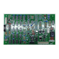
The C Option Engine Control PCB is a vital component responsible for managing the engine's overspeed shutdown function and setting the starter disengage speed. Proper calibration of this board prevents potential damage to the engine or alternator due to an overspeed condition, and protects the starter and ring gear from damage if the starter fails to disengage correctly. The adjustment process involves manipulating two potentiometers, COARSE (R26) and FINE (R27), in conjunction with observing a red LED on the PCB board to achieve the correct calibration. The goal is to set the overspeed shutdown to occur at approximately 72 Hz and ensure the starter disengages at around 500 rpm.

Important Technical Specifications:

  • Part Number: 0830890SRV (for the Control Board).
  • Affected Models: All generator sets utilizing a C Option control panel.
  • Adjustment Points: COARSE adjustment pot (R26) and FINE adjustment pot (R27) located on the circuit board.
  • Visual Indicator: A red LED on the PCB board, used to guide the adjustment process.
  • Overspeed Shutdown Target: Approximately 72 Hz.
  • Starter Disengage Speed Target: Approximately 500 rpm.
  • Normal Operating Speed: The engine should be at its rated speed (e.g., 62 Hertz for no-load) before and during the adjustment.
  • Adjustment Tools: No specific tools are mentioned beyond the need to turn the potentiometers, implying a small screwdriver or similar tool might be required.

Usage Features:

The adjustment procedure is a critical setup step for generator sets with the C Option control panel. It is not a routine user operation but rather a calibration performed during installation, maintenance, or troubleshooting of overspeed/starter disengagement issues. The procedure is designed to be followed meticulously to avoid potential damage.

The process involves:

  1. Initial Potentiometer Settings: Before starting the generator, the COARSE pot (R26) must be turned fully clockwise (CW), and the FINE pot (R27) must be turned fully counter-clockwise (CCW). This is a crucial safety step to prevent an overspeed shutdown at normal operating speed when the engine is first started.
  2. Engine Start and Stabilization: The generator engine is started manually and allowed to stabilize at its normal rated operating speed without a load. The engine governor may need adjustment to achieve this.
  3. COARSE Adjustment: While the engine is running at no-load and rated speed, the COARSE pot (R26) is slowly turned counter-clockwise (CCW) until the red LED on the PCB board just turns on.
  4. FINE Adjustment (Step 1): The FINE pot (R27) is then slowly turned clockwise (CW) until the red LED just goes out.
  5. FINE Adjustment (Step 2): Subsequently, the FINE pot (R27) is slowly turned counter-clockwise (CCW) until the red LED just turns back on. This final adjustment ensures the board is properly calibrated.
  6. Verification: The overspeed shutdown must be verified by manually increasing the engine speed until it shuts down. The shutdown should occur at approximately 72 Hz. If not, a slight adjustment of the FINE pot is necessary to achieve the correct shutdown speed. This verification also confirms the starter disengages at approximately 500 rpm.

Maintenance Features:

This adjustment procedure is a key maintenance task, particularly when replacing the control board or troubleshooting issues related to engine overspeed or starter engagement/disengagement. It is not a preventative maintenance item to be performed regularly without cause, but rather a corrective action or initial setup.

  • Troubleshooting: The procedure directly addresses "Overspeed and starter disengage calibration" problems. If a generator experiences these issues, this adjustment is the prescribed corrective action.
  • Safety Precaution: The document explicitly warns that steps 2 and 3 (initial potentiometer settings) MUST be completed before starting the engine. Failure to do so could result in an overspeed shutdown at normal operating speed, highlighting the importance of following the instructions precisely for both safety and proper function.
  • Damage Prevention: The document emphasizes that improper adjustment can lead to damage to the engine, alternator, starter, or ring gear, underscoring the critical nature of this calibration for the longevity and reliability of the generator set.
  • Documentation: The PIB references "MORE DETAILED INSTRUCTIONS from Generac Diagnostic Repair Manual # 79247," indicating that this procedure is part of a broader maintenance and repair framework, suggesting that trained technicians with access to full manuals are the intended audience for such adjustments. The inclusion of a diagram (Figure 1) showing the "Engine Control Circuit Board- Options A and B" with potentiometers R26 and R27, and the red LED, aids in locating the components for adjustment.

Generac Power Systems 0830890SRV Specifications

General IconGeneral
BrandGenerac Power Systems
Model0830890SRV
CategoryPortable Generator
LanguageEnglish

Related product manuals