TRANSFER SWITCH
PART 3
Page 73
INTRODUCTION
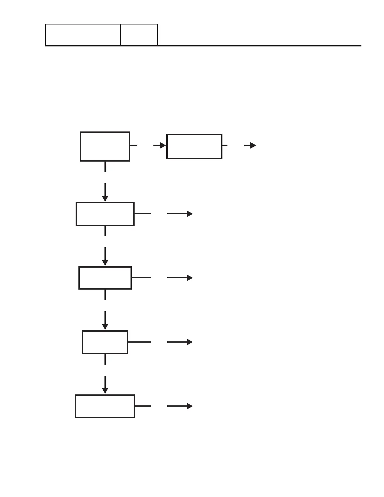
Use the “Flow Charts” in conjunction with the detailed instructions in Section 3.4. Test numbers used in the flow charts correspond
to the numbered tests in Section 3.4. The first step in using the flow charts is to identify the correct problem on the following pages.
For best results, perform all tests in the exact sequence shown in the flow charts.
Section 3.3
Troubleshooting Flowcharts
BAD
BAD
REPAIR OR REPLACE AS NEEDED
REPLACE
GOOD
GOOD
GOOD
FIND CAUSE OF NO AC OUTPUT
TO TRANSFER SWITCH FROM
GENERATOR
TEST 20 – CHECK
VOLTAGE AT
TERMINAL LUGS
E1 & E2
TEST 21 – CHECK
MANUAL TRANSFER
SWITCH OPERATION
TEST 22 – CHECK
23 AND 194
CIRCUIT
BAD
REPAIR AS NEEDED
TEST 24 – CHECK
STANDBY CONTROL
CIRCUIT
TEST 23 – TEST
TRANSFER
RELAY
BAD
TEST 30 – CHECK
MAIN LINE CIRCUIT
BREAKER
BAD
BAD
GOOD
REPAIR OR REPLACE MECHANISM
Problem 6 – With Controller in Automatic Mode and Utility Failed, Generator Runs but
Transfer to Standby Does Not Occur
 Loading...


