TRANSFER SWITCH
PART 3
Page 61
TRANSFER SWITCH CONTACTOR
The basic 2-pole CONTACTOR consists of a pair of moveable
LOAD contacts, a pair of stationary UTILITY contacts, and
a pair of stationary STANDBY contacts. The LOAD contacts
connect the UTILITY contacts by a utility closing coil or to the
STANDBY contacts using the standby closing coil. See Figures
60 and 61. In addition, the LOAD contacts can be moved to
either the “Utility” or “Standby” position by means of a manual
transfer handle. The closing coils are energized and actuated
by the voltage source from the side to which the load is being
transferred. I.e. If the CONTACTOR is in the “Utility” position,
the standby closing coil will energize utilizing Standby voltage.
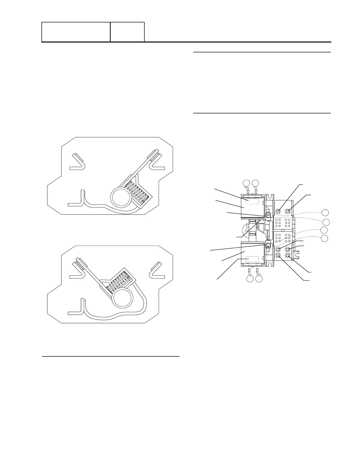
Figure 60. Load Connected to Utility Power Source
Figure 61. Load Connected to Standby Power Source
Utility Closing Coil C1
See Figure 62. The utility closing coil (C1) utilizes rectified
Utility source power to actuate the LOAD contacts to the
“Utility” position. When energized, the coil will move the LOAD
contacts to an “over center” position. A limit switch opens
the circuit and the spring force will complete the transfer
to “Standby”. The bridge rectifier, which changes the Utility
source alternating current (AC) to direct current (DC), is sealed
in the coil wrappings. If either the coil or the bridge rectifier
replacement becomes necessary replace the coil assembly.
Standby Closing Coil C2
The standby closing coil (C2) utilizes rectified Standby source
power to actuate the LOAD contacts to their “Standby” position.
Energizing the coil moves the LOAD contacts to an “over
center” position. A limit switch opens the circuit and the spring
force will complete the transfer to “Standby”. If either the coil
or the bridge rectifier replacement becomes necessary replace
the coil assembly.
Limit Switches SW2 and SW3
The LOAD contacts mechanically actuate the limit switches.
When the LOAD contacts connect to the UTILITY contacts, the
limit switch (SW2) opens the Utility circuit to C1 and the limit
switch (SW3) closes the Standby circuit to standby closing coil
(C2). The limit switches “arm” the system for transfer back to
the opposite source. An open condition in SW2 will prevent
retransfer to “Utility”. An open condition in SW3 will prevent
transfer to the “Standby.”
UTILITY
CLOSING
COIL (C1)
STANDBY
CLOSING
COIL (C2)
BRIDGE
RECTIFIER
BRIDGE
RECTIFIER
MANUAL
TRANSFER
LEVER
LIMIT
SWITCH
(SW2)
N1
N2
E2
E1
T1
LIMIT
SWITCH
(SW3)
T2
N2A A
A
B
126
205
B
E2
Figure 62. The “V-Type” Transfer Mechanism
TRANSFER RELAY
Transfer relay operation is controlled by the Nexus controller
mounted on the generator set. Figure 63 shows the transfer
relay electrical schematic. The transfer relay operates as
follows:
1. Generator battery voltage (12 volts DC) is available to the
transfer relay coil from the Nexus controller, via Wire 194
and Relay Terminal A.
a. The 12-volt DC circuit is completed through the transfer
relay coil and back to the controller via Wire 23.
Section 3.1
Description and Components
 Loading...


