EasyManua.ls Logo

Generac Power Systems 21-light - User Manual

Generac Power Systems 21-light
12 pages
Print Icon
To Next Page IconTo Next Page
Loading...
21-light
Remote Annunciator
Owner’s Manual

Questions and Answers

  • S
    Sarah BestAug 27, 2025
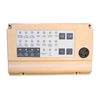
    How to troubleshoot no lights or LEDs lit on Generac Power Systems 21-light?
    • T
      tanyaowenAug 27, 2025
      If no lights or LEDs are lit on your Generac Power Systems Security System, check for the correct battery supply at terminal block J10 pins 1 and 2. J10 pin 1 should be + Battery (12 or 24 volts), and J10 pin 2 should be – Battery. Refer to the “power supply requirements” section at the beginning of the manual for cable specifications.
  • J
    James WestNov 4, 2025
    What to do if the Communication OK LED is flashing at one second ON/one second OFF on my Generac Power Systems 21-light?
    • R
      rachel84Nov 5, 2025
      If the “Communication OK” LED is flashing at the rate of one second ON/one second OFF on your Generac Power Systems Security System, verify that the RS485 communications cable meets specifications. Ensure the RS485 connections are properly connected (RS485+ to J10 pin 5, RS485– to J10 pin 6), and the shield/screen is connected correctly at the Generator end only. Also, check the RS485 cable installation between the Annunciator and the generator’s control panel, ensuring it is not sharing a conduit or running next to high voltage/current electrical lines. Finally, use the Generator Controller GenLink communication diagnostics to check data transmission/reception via the Tx and Rx check boxes in the “Com Ports” diagnostics menu. If no data is being transmitted/received, check the cabling. If...
  • D
    David SmithNov 15, 2025
    What to do if the Communication OK LED is flashing at 0.5 seconds ON/two seconds OFF on my Generac Power Systems 21-light Security System?
    • H
      hardincathyNov 15, 2025
      If the “Communication OK” LED on your Generac Power Systems Security System is flashing at a rate of 0.5 seconds ON/two seconds OFF, you should first check if the RS485 communications cable meets the required specifications. Then verify that the cable shield is correctly connected, ensuring it's connected at the Generator end only. Ensure proper installation of the RS485 cable between the Annunciator and the generator’s control panel, making sure it is not sharing a conduit or running near high voltage or high current electrical lines. Finally, use the Generator Controller GenLink communication diagnostics to see if data is being sent or received via the Tx and Rx check boxes. This can be found in the pull-down menu for diagnostics under “Com Ports”. If the check boxes do not change state,...

Summary

Annunciator Overview

Product Versions and Features

Details the 0G5719, 0G5720, and 0G5721 annunciator panel versions and their core features.

Core Functionality Explained

Explains how the annunciator monitors generator parameters, provides system warnings, and receives power.

Detailed Specifications

Environmental and Power Requirements

Covers operating temperature, humidity, power supply source, voltage, and usage details.

Communication and Relay Specifications

Outlines communication link, cable type, length, baud rate, relay outputs, and alarm relay specifications.

Transportation and Storage Guidelines

Provides temperature and humidity guidelines for transporting and storing the unit.

Installation and Mounting

Installation Compliance and Best Practices

Emphasizes adherence to codes, regulations, and manufacturer instructions for safe installation.

Wiring and Cable Management

Guides on using knockouts for wire routing and wire tie-downs for cable strain relief.

Relay Annunciation Configuration (J1-J8)

Explains selecting generator parameters for relays using DIP switches S1 and S2.

Parameter Selection Examples

DIP Switch Settings and Examples

Illustrates parameter assignment to relays using DIP switch settings with practical examples.

Generator Parameters and Indicators

Parameter Definitions Explained

Defines key generator parameters like Run, Power, Line Power, and Battery Charger AC Failure.

Generator Status and Warning Indicators

Details red and yellow indicator lights and audible alarms for generator stop and warning conditions.

System Status and Controls

System Status LED Functions

Explains the System Ready, Communication OK, and internal Green Status LEDs.

Keypad Switch Operations

Describes the operation of the Test, Re-arm Horn, and Reset switches on the annunciator.

Configuration Options and Other Functions

Spare Keypad Switch and Remote Start

Details the functionality of the Spare Keypad Switch for Relay 8 control and Remote Start capability.

Interface and Communication Settings

Covers GUI enablement, Master/Slave mode, and Baud Rate selection via DIP switches.

Communication Interface Details

Alarm Relay and RS485 Termination

Explains the Alarm Relay (J9) operation and the RS485 line termination resistor setup.

GUI, RS485 Comms, and Connect Time

Details the GUI, RS485 communication modes, and the initial connection time for the annunciator.

Operational Guidelines and Reference

Error Handling and Communication Limits

Provides guidance on error reporting, handling, and communication restrictions for RS485 networks.

Terminology and Abbreviations

Lists definitions for common terms and abbreviations used throughout the manual.

Troubleshooting Guide

Common Annunciator Issues and Solutions

Guides on resolving issues like no lights, Communication OK LED flashing, or Green Status LED flashing.

Generac Power Systems 21-light Specifications

General IconGeneral
BrandGenerac Power Systems
Model21-light
CategorySecurity System
LanguageEnglish