3
Remote Annunciator
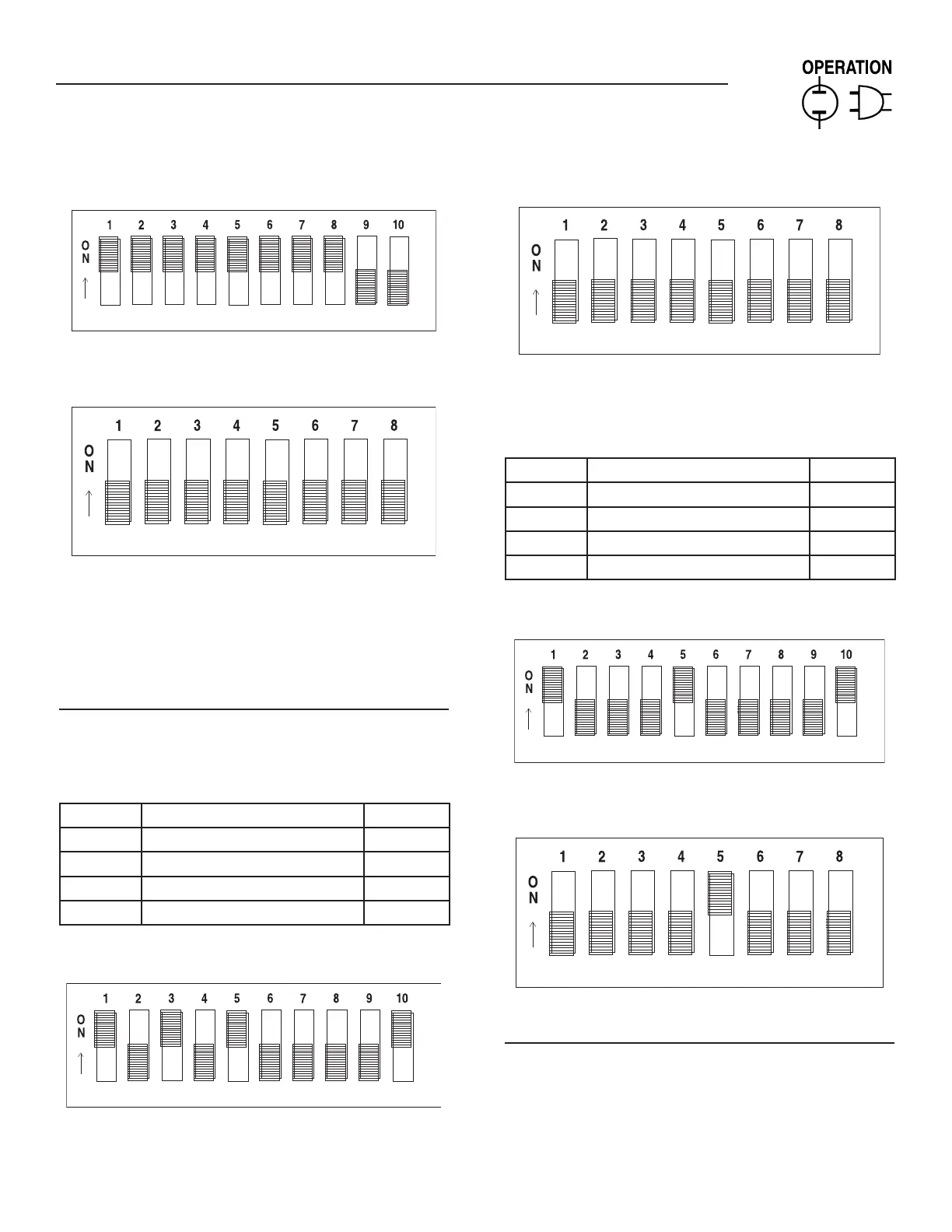
Figure 4 — DIP Switch S1 Settings
Figure 5 — DIP Switch S2 Settings
NOTE:
6. If a unit is wired up and then subsequently an additional
DIP switch position is selected or deselected, all the relay
outputs are re-assigned sequentially and therefore the
annunciator terminals may require re-wiring.
PARAMETER SELECTION EXAMPLES
Example 1
DIP S1-1, 3, 5, 10 are initially selected, these are assigned to
relays 1, 2, 3, 4 (Figures 6 and 7).
DIP Parameter Relay
1, 1 RPM Sensor Loss 1
1, 3 Overspeed 2
1, 5 High Water Temp/Low Water Level 3
1, 10 Pre-Low Fuel 4
Figure 6 — S1
Figure 7 — S2
Example 2
If subsequently DIP1-3 is removed, and DIP2-5 is added, then
relays will be re-assigned (Figures 8 and 9).
DIP Parameter Relay
1, 1 RPM Sensor Loss 1
1, 5 High Water Temp/Low Water Level 2
1, 10 Pre-Low Fuel 3
2, 5 Generator Power 4
Figure 8 — S1
Figure 9 — S2
PARAMETERS S1.1 - S1.10 & S2.1 - S2.3
When a remote annunciator (0G5719) or Remote Relay Panel
(0G5720) is used in a Modular Power System (MPS), an alarm on
any one of the generators causes the associated relay to activate.