4
PARAMETER "GENERATOR RUN"
This parameter is defined as any one or more generators in the
system running.
PARAMETER "GENERATOR POWER"
This light/LED indicates different things depending on the type of
system it is attached to.
It is defined as whether the Transfer Switch is in the Generator •
Supply Position.
For a PowerManager System Controller (PM-SC with external •
transfer switch(es)), generator power is defined as any one or
more generators in the system running and connected to the
generator bus.
For a non-paralleling engine controller (PM-GC • WITHOUT inter-
nal transfer switch), it represents the status of input 4 (TB2-5)
to the generator controller. This should be connected to the gen-
erator side auxiliary contact of the external transfer switch. A
closure to ground will cause the light to illuminate. This shows
whether the load is powered by the generator.
For an engine controller that is part of an MPS system, genera-•
tor power represents the state of the internal contactor that the
generator is connected to.
PARAMETER "LINE POWER"
This light/LED indicates different things depending on the type of
system it is attached to.
Is defined as whether the Transfer Switch is in the Utility Supply •
Position.
For a Power Manager System Controller (PM-SC with external •
transfer switch(es)), line power represents the auxiliary input
C (TB6-4).
For a non-paralleling engine controller (PM-GC WITHOUT inter-•
nal transfer switch), it represents the status of input 3 (TB2-4)
to the generator controller. This should be connected to the
utility side auxiliary contact of the external transfer switch. A
closure to ground will cause the light to turn ON. This shows
whether the load is power by the utility.
For an engine controller that is part of an MPS system, line •
power is not used.
PARAMETER “BATTERY CHARGER AC FAILURE”
This light/LED annunciates upon loss of 120VAC power supply to
the battery charger and is communicated to the Annunciator by the
generator controller.
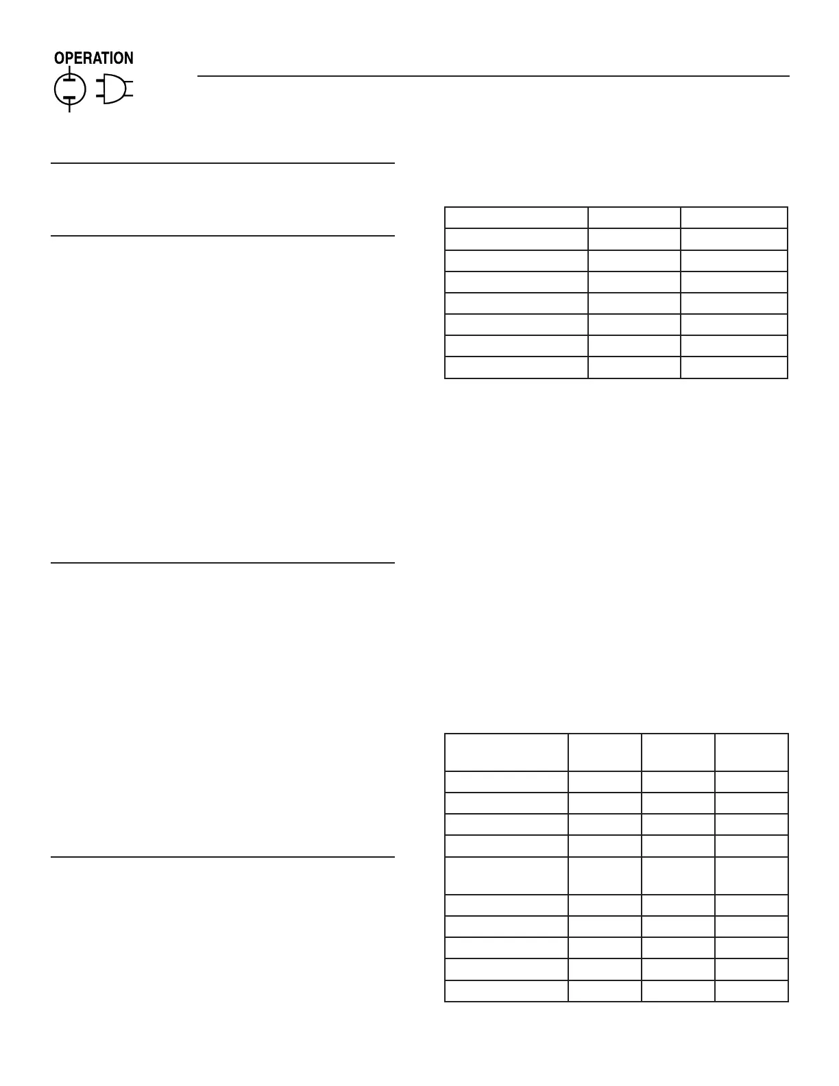
GENERATOR STOP INDICATORS
These lights/LEDs will flash when any alarm occurs and the horn
will sound as follows:
Annunciator Light Light Color Audible Alarm
RPM Sensor Loss Red Yes
Overcrank Red Yes
Overspeed Red Yes
Low Oil Pressure Red Yes
High Water Temp Red Yes
Low Water Level Red Yes
Emergency Stop Red Yes
NOTE:
7. Both the High Water Temp and the Low Water Level LEDs will
turn ON if either fault condition is present.
The "Re-arm Horn" switch can be used to turn off and re-arm the
horn, or the alarms can be fully acknowledged using the "Reset"
switch.
The "Reset" switch will turn off and re-arm the horn, and any flash-
ing lights will switch to the ON state until the alarms are no longer
present at the generator control panel.
NOTE:
8. The alarm condition must be reset at the generator control
panel.
9. When this annunciator is used in a Modular Power System
(MPS), an alarm on any one of the generators will cause the
lights/LEDs to light, and alarms to sound.
WARNING INDICATORS
These lights/LEDs will flash when any alarm occurs and the horn
will sound according to the following table:
Annunciator Light Light Color Audible
Alarm
Latched
Pre-low Oil Pressure Yellow Yes Yes
Pre-high Water Temp Yellow Yes Yes
Pre-low Water Temp Yellow Yes Yes
Pre-low Fuel Yellow Yes Yes
Battery Charger AC
Failure
Yellow Yes No
Low Battery Voltage Yellow Yes No
High Battery Voltage Yellow No No
Generator Run Yellow No No
Generator Power Yellow No No
Not in Auto Red Yes No
Remote Annunciator