6
Section 1 — General Information
Air-cooled Generators
1.5 THE GENERATOR
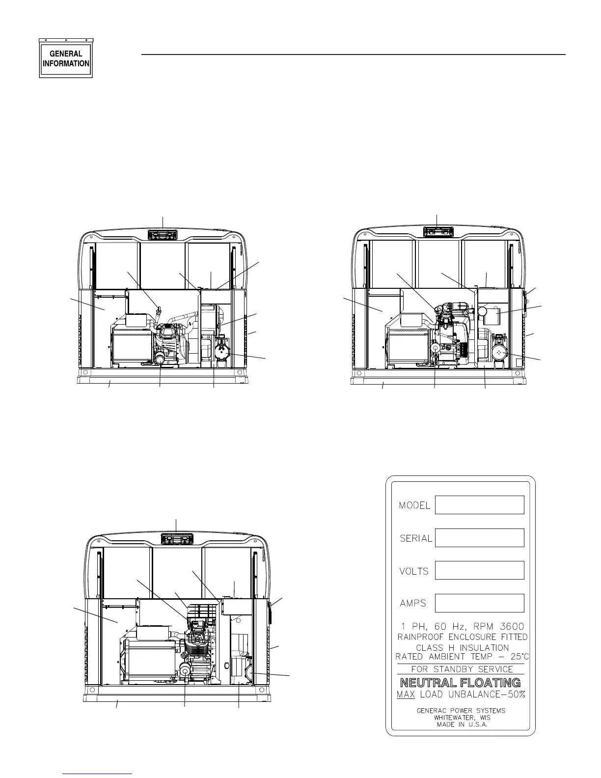
Roof Latch
Data Label
(see sample)
Oil
Dipstick
Exhaust
Enclosure
Composite Base Oil Filter Battery Compartment
Fuel
Regulator
Fuel Inlet
(back)
Air Filter
Circuit
Breaker
Control
Panel
Roof Latch
Data Label
(see sample)
Oil
Dipstick
Exhaust
Enclosure
Composite Base Oil Filter Battery Compartment
Fuel
Regulator
Fuel Inlet
(back)
Air Filter
Circuit Breakers
GFCI Outlet
(All 17 & 20kW)
Control
Panel
Figure 1.3 – 12, 14, 16, 17 and 20kW, V-twin,
GT-990/GT-999 Engine (door removed)
Figure 1.1 – 8kW, Single Cylinder, GH-410 Engine
(door removed)
Roof Latch
Data Label
(see sample)
Oil
Dipstick
Exhaust
Enclosure
Composite Base Oil Filter Battery Compartment
Fuel
Regulator
Fuel Inlet
(back)
Air
Filter
Circuit
Breaker
Control
Panel
Figure 1.2 – 10kW, V-twin, GT-530 Engine
(door removed)
Data Label Sample