4 Owner’s Manual for Portable Generator
Section 2 General Information and Setup
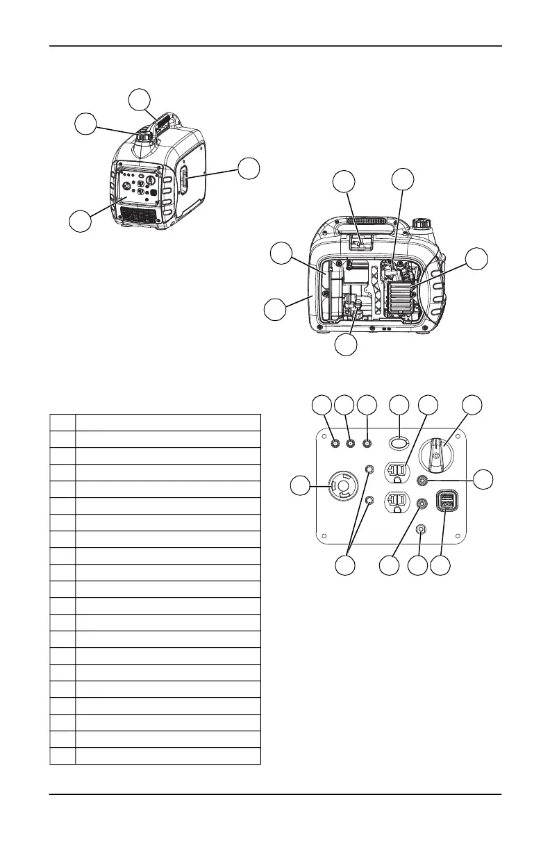
Figure 2-1. Features and Controls
TABLE 1. Generator Components
Figure 2-2. Control Panel
005678
10
19
16
17
12
11
14
006087
18
21
15
1 Low Oil LED (Red)
2 Overload LED (Red)
3 AC Power LED (Green)
4 Economy Mode Switch (ECO)
5 1A/2.1A, 5 VDC USB Outlet
6 AC Breaker
7 Parallel Operation Cable Connection
8 Grounding Location
9 120V, 20A Receptacle (NEMA 5-20R)
10 Handle
11 Fuel Tank Cap
12 Control Panel
13 PowerDial™
14 Recoil Starter
15 Muffler
16 Oil Fill/Drain
17 Air Cleaner
18 Carburetor
19 Spark Plug
20 120V, 30A Receptacle (NEMA L5-30R)
21 Spark Arrestor
1 2 3
7
13
6
4
5
9
20
011948
7
8