4-2
SECTION 4: GOVERNOR CONTROLS AND GOVERNOR
GOVERNOR ARM
If the governor arm does not move freely, or if the arm feels loose in the
bushings, it may need replacing. If wear is noticed, change the gov-
ernor arm, governor gear assembly (gear and flyweights), spool, and
bushings as needed. Lubricate all moving parts when reassembling.
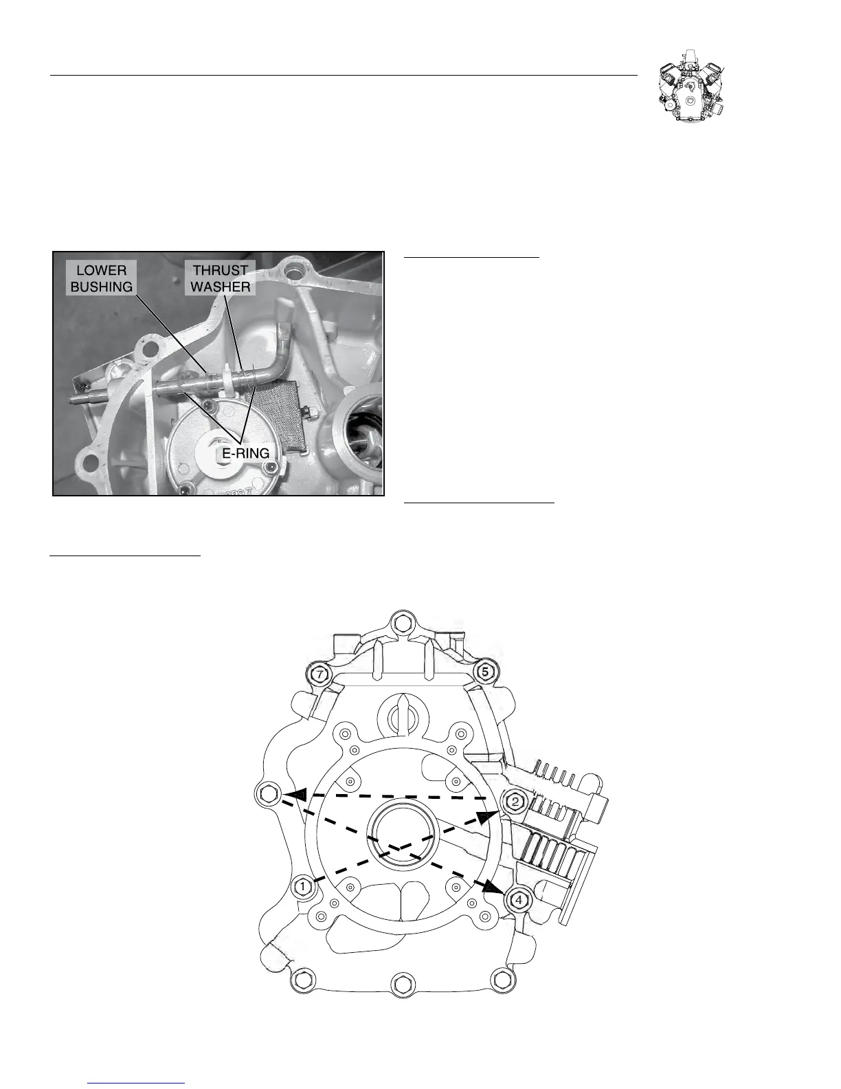
Figure 4-3. Governor Arm Assembly
DISASSEMBLE GOVERNOR ARM:
1. Remove the e-clips.
2. Slide the arm down and out of the bushings.
3. Replace any parts that appear worn.
Note: The lower bushing is a slip fit, and the upper bushing is
pressed in.
ASSEMBLE GOVERNOR ARM:
1. Slide the thrust washer part way onto the new governor
arm.
2. Insert the governor arm in the lower bushing holder, and slide it
part way in.
3. Install lower e-clip on the arm, and slide the thrust washer down
to it.
4. Slip the lower bushing part way on to the arm.
5. Slide the arm in until the thrust washer is tight.
6. Slide the lower bushing down and into it’s holder, then install the
upper e-clip.
ASSEMBLE CRANKCASE COVER:
1. Clean any old gasket material from the crankcase and cover
mating surfaces.
2. Be sure that the new oil passage o-ring is in place (see
Figure 4-1).
TOR
UE SE
UENCE FOR
RANK
A
E
VER:
1-2-
-4-
-
-7-
-
-1
1
Figure 4-4. Crankcase Bolt Torque Sequence