SECTION 5: CYLINDER HEAD AND VALVES
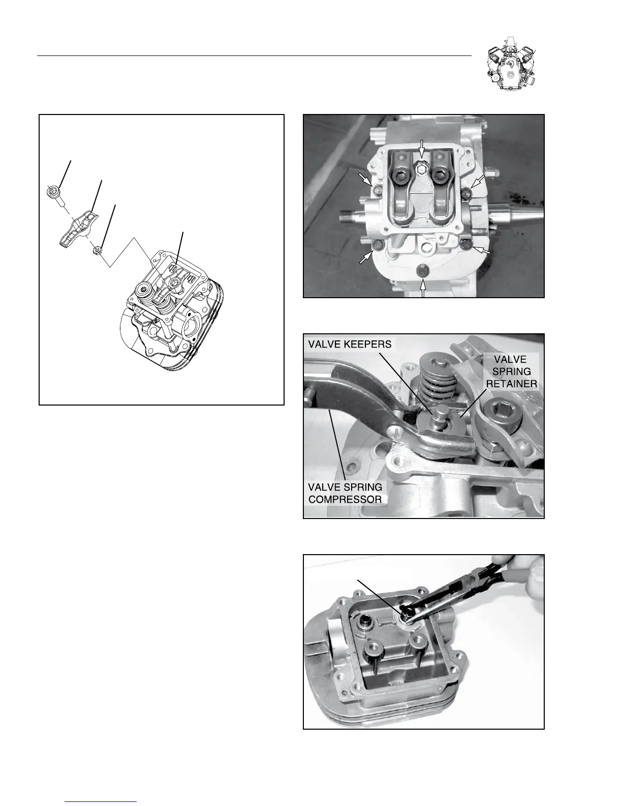
BALL STUD
ROCKER ARM
JAM NUT
PUSH ROD GUIDE
(TABS MUST FACE UPWARD)
Figure 5-3.
3. Remove push rod guide plate.
4. Remove head bolts and cylinder head (Figure 5-4).
a. Discard gasket.
5. Repeat Steps 1-4 for other cylinder head.
DISASSEMBLE CYLINDER HEAD
1. Place a shop rag or short section of rubber fuel line under
valves inside combustion chamber to hold valve in place while
compressing spring.
2. Hold down valve spring retainer with a valve spring compressor
(Figure 5-5). Remove the following:
a. Valve spring keepers
b. Valve spring retainer
c. Valve spring
d. Intake and exhaust valves
3. Remove and discard valve stem seals (Figure 5-6).
Figure 5-4. Remove Cylinder Head
Figure 5-5. Removing Retainers
VALVE STEM SEAL
(USED ONLY ON INTAKE SIDE)
Figure 5-6. Removing Valve Stem Seals
5-2