13-1
SECTION 13: ENGINE ASSEMBLY
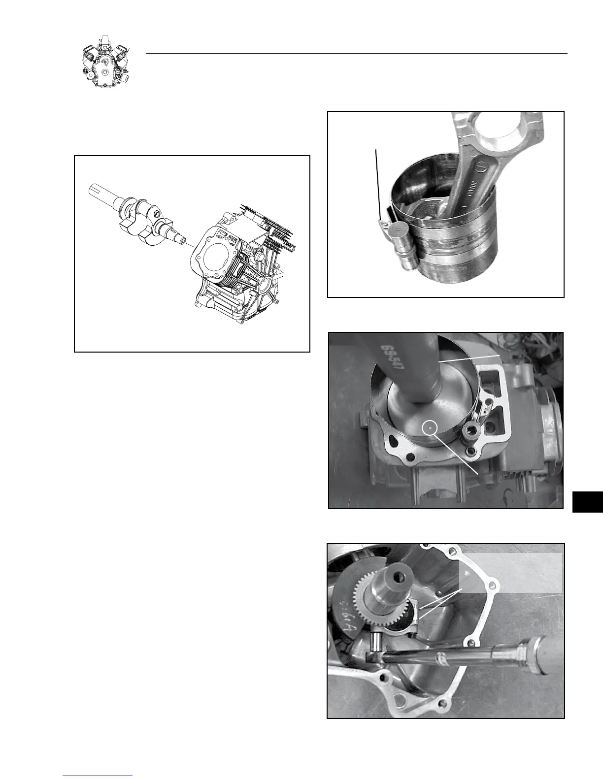
INSTALL CRANKSHAFT
Lubricate magneto bearing and inside edge of oil seal with engine oil
and install crankshaft.
Figure 13-1. Installing Crankshaft
INSTALL PISTON AND CONNECTING ROD
Note: Install #1 piston and connecting rod first.
1. Lubricate piston rings, piston skirt, and Ring Compressor, with
oil.
a. Rotate the rings so that the ring end gaps are 90 degrees from
each other.
b. Place piston inside of ring compressor and set upside down on
bench with projections on compressor facing up Figure 13-2.
c. Tighten ring compressor until rings are fully compressed.
d. Remove connecting rod cap.
2. Lubricate cylinder bores and crankpin and rotate crankshaft until
it is at bottom of stroke.
3. Install #1 piston with notch or casting mark towards flywheel
side. See Figure 13-3.
a. Push piston down by hand, or with a wood handle, until
connecting rod is seated on crankpin.
4. Assemble connecting rod cap to rod with match marks aligned,
Figure 13-4.
a. Torque screws to 24.4 Nm (216 in. lbs.).
5. Rotate crankshaft two revolutions to check for binding. Rod should
also be free to move sideways on crankpin.
Repeat Steps 1-5 for #2 cylinder.
RING
COMPRESSOR
Figure 13-2. Compressing Rings
NOTCH OR
CASTING MARK
TOWARD
FLYWHEEL SIDE
HAMMER
HANDLE
Figure 13-3. Installing Piston And Connecting Rod
ALIGN MARKS ON
ROD AND CAP
WHEN ASSEMBLING
Figure 13-4. Torque Connecting Rods (#2 rod shown)
13