13-3
SECTION 13: ENGINE ASSEMBLY
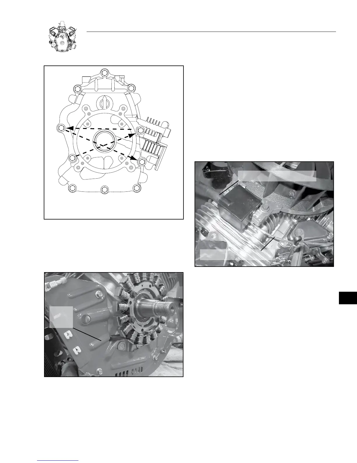
TORQUE SEQUENCE FOR
CRANKCASE COVER:
1-2-3-4-5-6-7-8-9-10
7
9
5
2
4
8
10
6
1
3
Figure 13-9. Crankcase Cover Torque Sequence
INSTALL ALTERNATOR AND IGNITION COILS
1. Install alternator, Figure 13-10.
a. Torque screws to 4.75 Nm (40 in. lbs.).
BACK
PLATE
RELIEF
Figure 13-10. Install Alternator
2. Install back plate.
a. Torque screws to 4.75 Nm (40 in. lbs.).
Important: Route alternator wires through relief in back plate.
DO NOT pinch wires.
3. Assemble ignition coils to engine, Figure 13-11.
a. Mounting holes in coil are slotted. Push coil as far back as pos-
sible and tighten one screw to hold coil in place.
4. Repeat for second coil.
Note: The spark plug lead must be at the top.
5. Install ground wire onto tab terminal on ignition coils.
Important : Make sure wires are routed over coil mounting posts
and under breather tube.
6. Install starter motor.
a. Torque screws to 27 Nm (228 in. lbs.).
GROUND WIRE ROUTING
SPARK PLUG LEAD AT TOP
Figure 13-11. Ignition Coils
INSTALL BREATHER
1. Insert baffle if equipped.
2. Insert breather material.
3. Install breather assembly and gasket.
4. Torque bolts to 4.75 Nm (40 in. lbs.).
INSTALL FLYWHEEL
Important: Clean flywheel and crankshaft taper removing all oil,
dirt or grease.
1. Insert flywheel key into crankshaft.
2. Assemble flywheel to crankshaft.
3. Install washer (cupped side down) and flywheel nut.
4. Torque flywheel nut to 214 Nm (150 ft. lbs.), Figure 13-12.
13