1
2
5
7
6
3
4
1
2
3
4
5
6
7
8
8
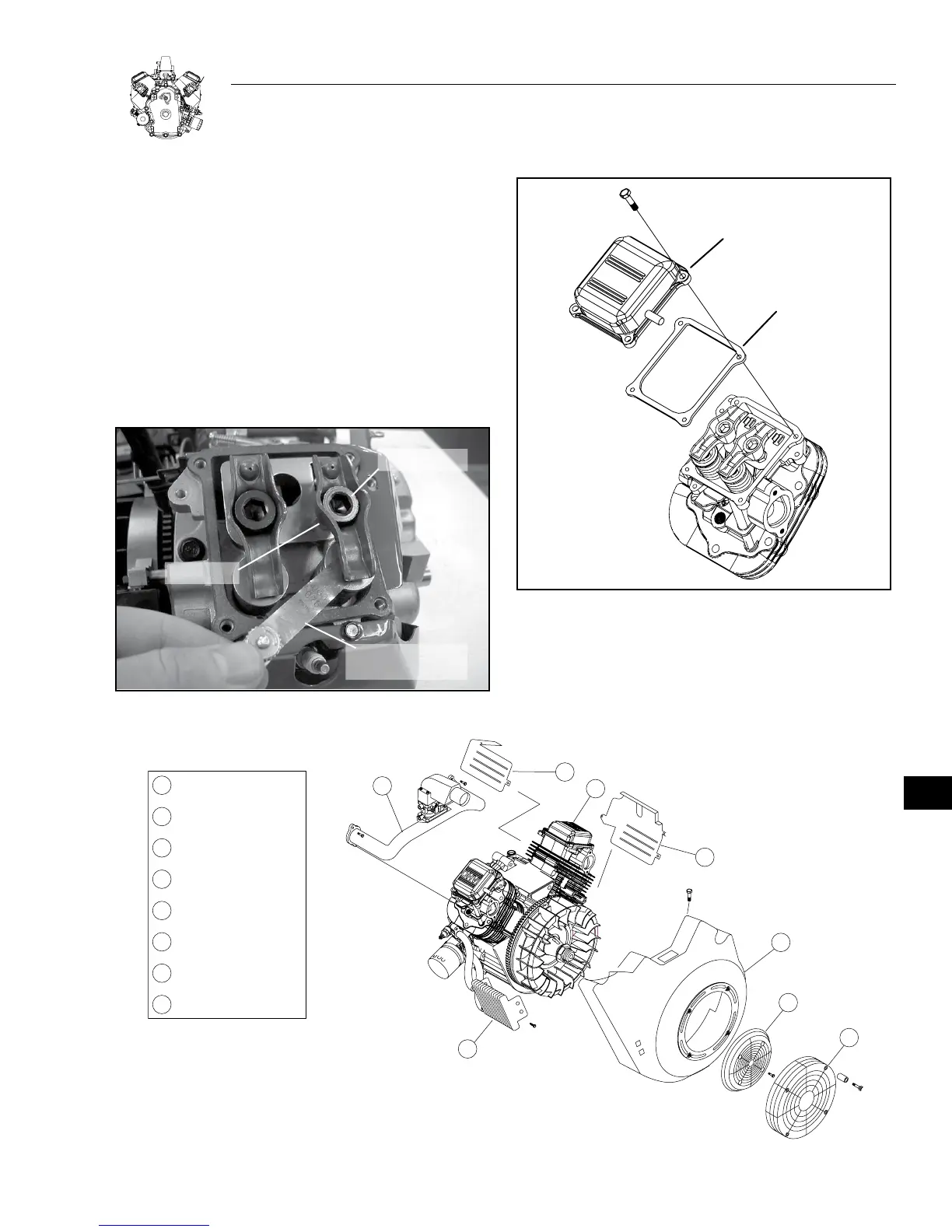
VALVE COVER
LOWER WRAPPER
UPPER WRAPPER
BLOWER HOUSING
OIL COOLER
INTAKE MANIFOLD
ASSEMBLY
ROTATING SCREEN
FINGER GUARD
13-5
SECTION 13: ENGINE ASSEMBLY
ADJUST VALVE CLEARANCE
1. Set No. 1 cylinder at TDC (Top Dead Center), compression
stroke.
a. Adjust rocker arms to specified clearance, Figure 13-16.
Valve Clearance (cold) INTAKE and EXHAUST:
0.076mm, +/- 0.02mm (.003" +/- .001")
b. Torque ball stud jam nuts to 19 Nm (168 in. lbs.).
2. Repeat for No. 2 cylinder.
3. Install valve covers with new gaskets, Figure 13-17
a. Torque bolts to 6.8 Nm (60 in. lbs.).
0.076 mm
(0.003") GAUGE
JAM NUT
BALL STUD
Figure 13-16. Adjust Valve Clearance
VALVE COVER
GASKET
Figure 13-17. Install Valve Covers and Gaskets
GENERAL ASSEMBLY
1. Install cylinder wrappers.
a. Torque M5 screws to 2.8 Nm (25 in. lbs.).
Figure 13-18. Install Blower Housing
13