SPECIFICATIONS
Engine Type . . . . . . . . . . . . . . . . . . . . . . . . Single Cylinder, 4-Stroke
Engine Size . . . . . . . . . . . . . . . . . . . . . . . . . . . . . . . . . . . . . . 127cc
Starter Type . . . . . . . . . . . . . . . . . . . . . . . . . . . . . . . . . . . . . . Recoil
Fuel Capacity/Type . . . . . . . . . . . . . . . . . . . .1.0 Gal (3.8L)/Unleaded
Oil Capacity . . . . . . . . . . . . . . . . . . . . . . . . . . . . . . . . 0.63 Qt (0.6L)
Runtime Full/Half Load . . . . . . . . . . . . . . . . . . . . . . . . 2.8/4.7 Hours
Spark Plug Type. . . . . . . . . . . . NGK CR5H88 or Denso U16FSR-UB
Spark Plug Gap . . . . . . . . . . . . . . . . . . . . . . . . . . . . . . . . . . . ..030”
Dimensions L x W x H (in) . . . . . . . . . . . . . . . . . . . . . . 22 x 12 x 18
Weight Lb/kg . . . . . . . . . . . . . . . . . . . . . . . . . . . . . . . . . . 49.6/22.5
Maximum AC Output . . . . . . . . . . . . . . . . . . . . . . . . . . . . . . 2000W
Surge AC Output . . . . . . . . . . . . . . . . . . . . . . . . . . . . . . . . . 2200W
AC Volts. . . . . . . . . . . . . . . . . . . . . . . . . . . . . . . . . . . . . . . 120 VAC
Rated AC Current . . . . . . . . . . . . . . . . . . . . . . . . . . . . . . . . . .16.7 A
Frequency . . . . . . . . . . . . . . . . . . . . . . . . . . . . . . . . . . . . . . . 60 Hz
THD. . . . . . . . . . . . . . . . . . . . . . . . . . . . . . . . . . . . . . . . . . . . . 3.0%
Insulation Class . . . . . . . . . . . . . . . . . . . . . . . . . . . . . . . . . . Class B
Outlets. . . . . . . . . . . . . . . . . . . . . . . . . . . . . .(2) 5-20R, (1) 12 VDC
DC Volts. . . . . . . . . . . . . . . . . . . . . . . . . . . . . . . . . . . . . . . . 12 VDC
Rated DC Current. . . . . . . . . . . . . . . . . . . . . . . . . . . . . . . . . . . . 5 A
NOTE:
Power output and runtime are influenced by many factors,
some of which are fuel quality, ambient temperature and engine
condition. Output decreases approximately 3.5% for each 1,000
feet above sea level and 1% for every 10 degrees above 60°F.
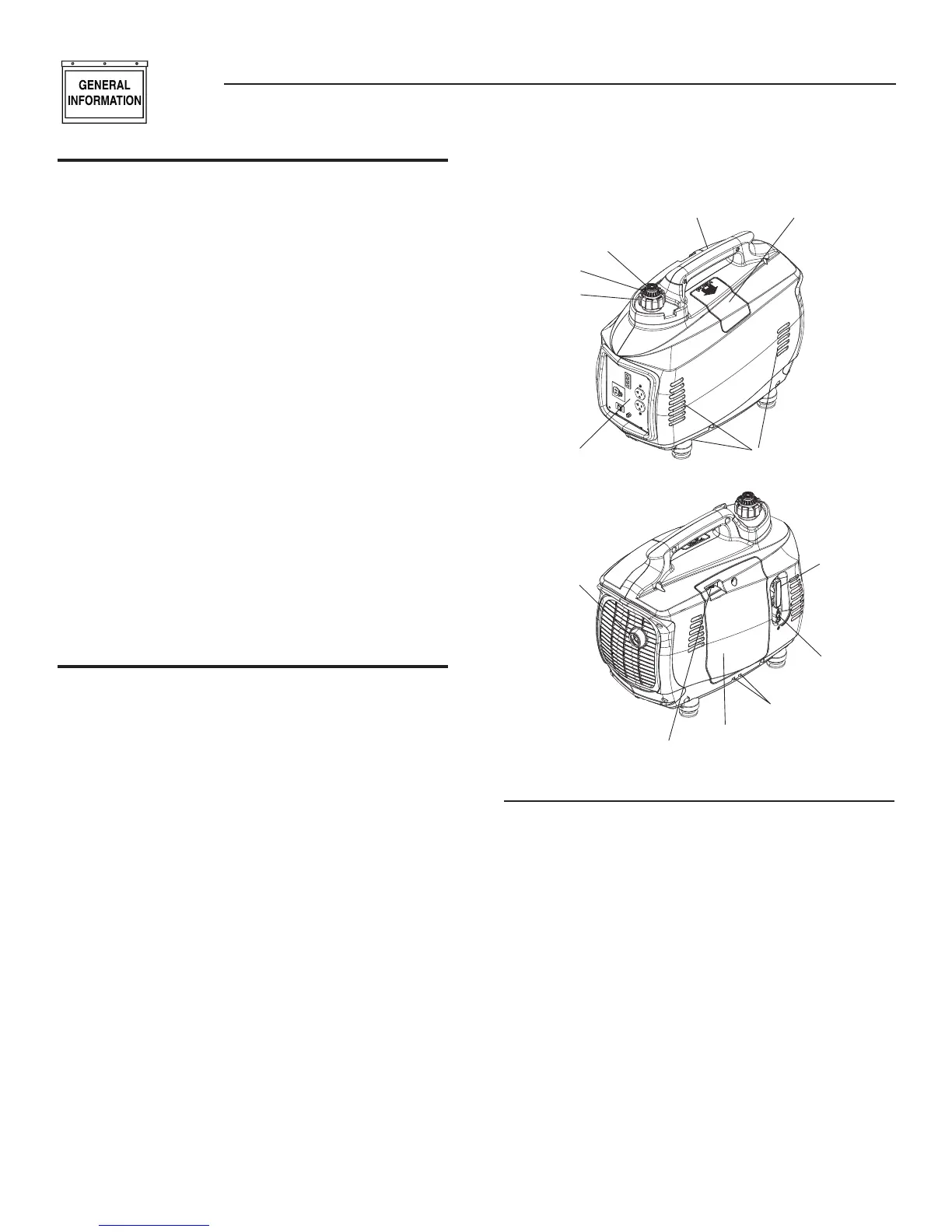
UNIT IDENTIFICATION (Figure 2)
1. Carrying Handle: Lift the generator by this handle only.
2. Spark Plug Cover: Allows access to the engine spark plug.
3. Fuel System Primer: Used to prime the fuel system for
starting.
4. Fuel Cap Pressure Valve: Allows air to enter the fuel tank to
equalize pressure.
5. Fuel Tank Cap: Access to fuel tank for filling.
6. Control Panel: location of generator controls and output
receptacles.
7. Air Intake Slats: Allows for cooling air to enter the housing.
8. Muffler: Lowers engine exhaust noise.
9. Choke: Cold engine starting aid
10. Left Side Service Cover: Allows access to air filter, fuel filter
and oil fill/dipstick.
11. Vent Hoses: Hoses allow venting of the crankcase and
carburetor.
12. Fuel Shutoff: Controls fuel supply to the carburetor.
13. Starter Rope: Pull rope for starting engine.
Figure 2 - Unit Identification
1
2
3
4
5
6
7
8
9
10
11
12
13
CONTROL PANEL X (Figure 3)
14. Low Oil Level LED (yellow): Lights up when oil level is below
safe operating level.
15. Overload LED (red): Lights up if the generator experiences a
load greater than the rated output.
16. Ready LED (green): Indicates output from the generator unless
there is a low oil or overload condition.
17. 12 VDC Plug: Connection for re-charging 12VDC automotive-
style batteries while generator is in operation.
18. FlexPower™ Switch: This switch slows the engine speed
when the load is reduced to save fuel and engine wear.
19. 12 VDC Circuit Breaker: Overload protection for the 12 VDC
charging system.
20. Ground (Earth) Connection Lug: Grounding point for the
generator; consult state and local electrical codes before use
(floating ground).
21. 120 VAC Receptacles: Two (2) receptacles for connecting
accessories.
NOTE:
Do not exceed the rated output of the generator.
4
Section 1 – General Information
Portable Generator System
 Loading...