General Information
36949 B MMG25I-35D-45I-55DF4 Operating Manual 13
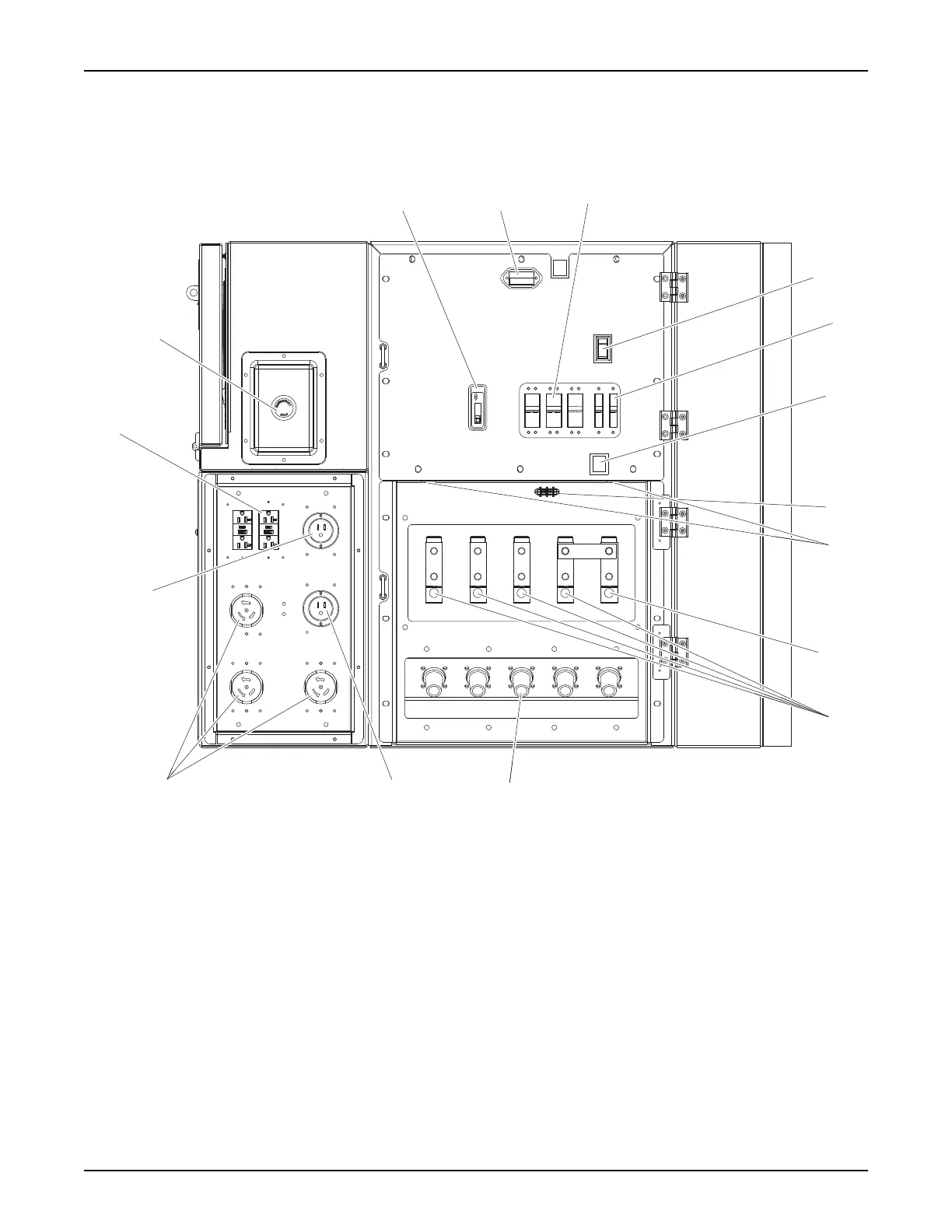
Figure 2-5. Control Panel (Right Side of Unit)
1. Main circuit breaker 9. Connection lugs (4)
2. Control panel lights (3) 10. Cam lock connection lugs (5) (optional)
3. 50A circuit breakers (3) 11. Connection for optional equipment inlet
4. Service lights switch 12. 120V/240V twist-lock receptacles (3)
5. 20A circuit breakers (2) 13. Connection for battery charger
6. Lug door safety switch 14. 120V GFCI receptacles (2)
7. Remote start terminal block 15. Emergency stop switch
8. Ground connection lug
1
2
3
4
5
6
8
9
10
12
13
14
15
01882
7
2
11
 Loading...