ALTERNATOR AC LEAD
CONNECTIONS
See “Voltage Codes”. This Stationary Emergency Generator may
be rated at any one of three voltages, either single-phase or three-
phase. The electrical wires in the unit’s AC connection (lower)
panel should be installed according to the number of leads and the
voltage/phase required for the application. If there are any ques-
tions regarding lead connection, refer to the wiring diagrams at the
back of this manual.
Voltage codes apply to the type of stator assembly installed on a
particular generator.
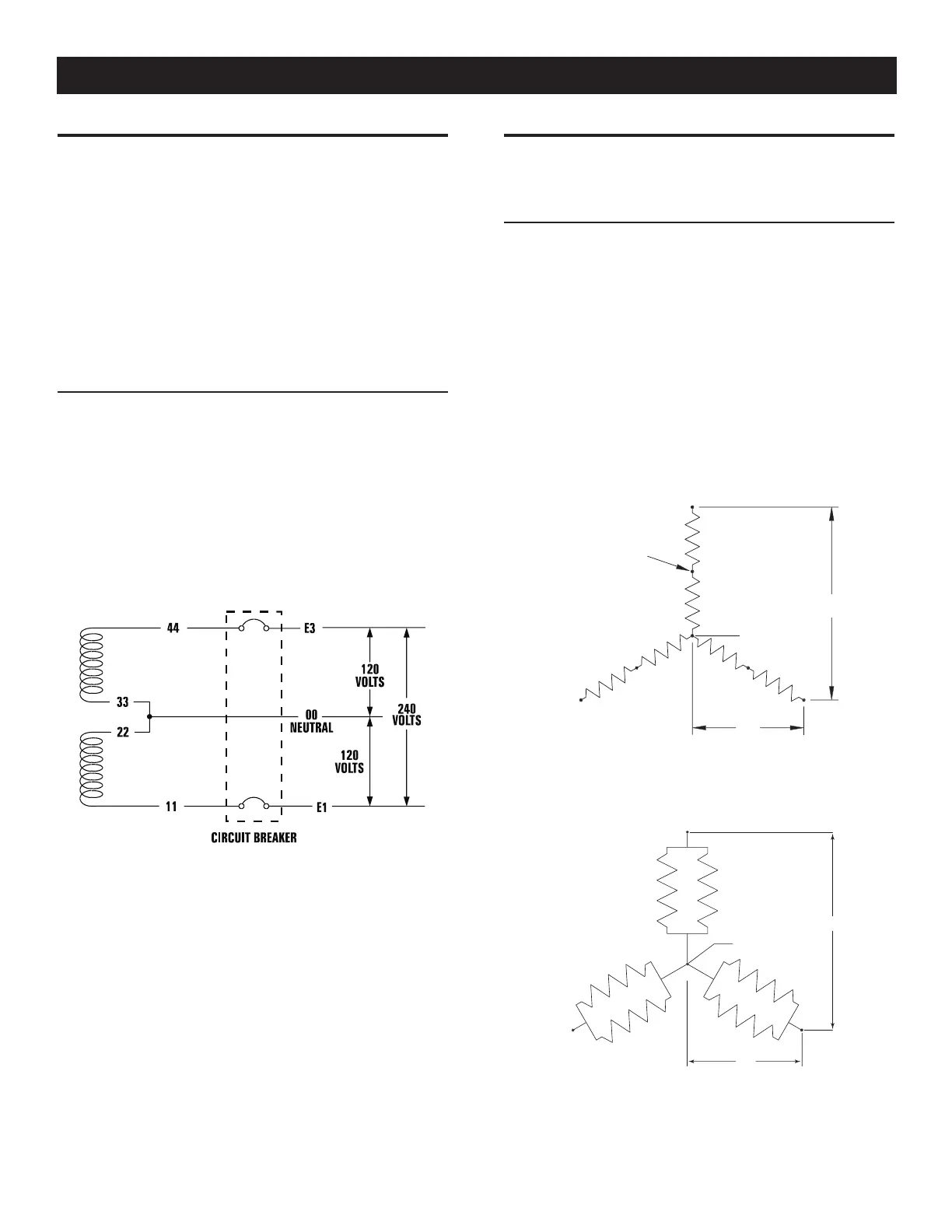
FOUR-LEAD, SINGLE-PHASE STATOR
Four-lead alternators (see Figure 7.1) are designed to supply elec-
trical loads with voltage code “A” (240V, 1-phase, 60 Hz). Electrical
power is produced in the stator power windings. These windings
were connected at the factory to the main circuit breaker as shown
in Figure 7.1.
The rated voltage between each circuit breaker terminal is 240V.
The rated voltage between each circuit breaker terminal and the
neutral point 00 is 120V.
Figure 7.1 — Four-lead, Single-phase Stator
ALTERNATOR POWER WINDING
CONNECTIONS
3-PHASE ALTERNATORS
The Stationary Emergency Generator is designed to supply
3-phase electrical loads. Electric power is produced in the alterna-
tor power windings. These windings were connected at the factory
to the main circuit breaker with a “Y” configuration as shown in
Figures 7.2 and 7.3.
The rated voltage between circuit breaker terminals E1-E2, E1-E3
and E2-E3 is either 480V or 208V depending on the model.
The rated voltage between each circuit breaker terminal and the
neutral point 00 is either 277V or 120V depending on the model.
Figure 7.2 — Stator Power Winding
Connections - 3-phase, 277/480V (6 Lead)
E
NNE
TI
N
L-
-
NE
TRA
Figure 7.3 — Stator Power Winding
Connections - 3-phase, 120/208V (6 Lead)
E
00
NEUTRAL
-
-
S
7-1
ACConn001 Rev. B 06/10
General Information
 Loading...