10
2.4 BASIC STANDBY ELECTRIC
SYSTEM
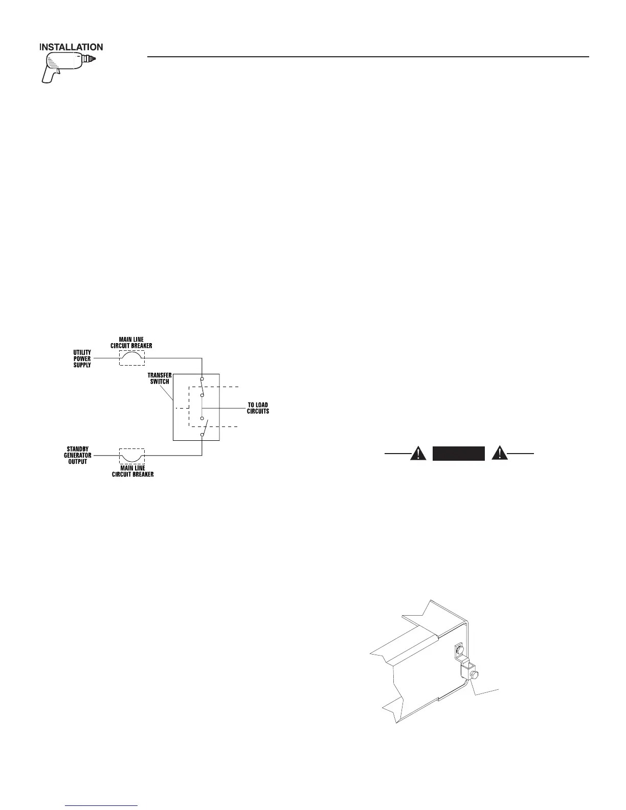
Figure 2.1 shows a schematic diagram of a basic
standby electric system. Both the UTILITY power
supply and the STANDBY (GENERATOR) output are
connected to an approved transfer switch. The trans-
fer switch is required by electrical code and serves
the following functions:
• Allows the LOAD circuits to be connected to only
one power supply at a time.
• Prevents electrical backfeed between the generator
and the UTILITY power circuits.
Notice that both the STANDBY and the UTILITY
power supplies to the transfer switch are protected
against overload by a main line circuit breaker.
Figure 2.1 – Basic Standby Electric System
2.5 EMERGENCY CIRCUIT ISOLATION
METHOD
This prevents overloading the generator by keeping
electrical loads below the wattage/amperage capac-
ity of the generator. If the generator is powering only
critical loads, within the wattage/amperage capac-
ity, during utility power outages, consider using the
emergency circuit isolation method.
Critical electrical loads are grouped together and
wired into a separate “Emergency Distribution Panel.”
Load circuits powered by that panel are within the
wattage/amperage capacity of the generator set. When
this method is used, it is difficult to overload the gen-
erator. The transfer switch must meet the following
requirements:
• It must have an ampere rating equal to the total
amperage rating of the emergency distribution
panel circuit.
• Have it installed between the building’s main dis-
tribution panel and the emergency distribution
panel.
2.6 TOTAL CIRCUIT ISOLATION
METHOD
When a generator capable of powering all electrical
loads in the circuit is to be installed, use the “Total
Circuit Isolation Method.” It is possible for the gen-
erator to be overloaded when this isolation method is
employed. The following apply to the transfer switch
in this type of system.
• Ampere rating of the transfer switch must equal
the ampere rating of the normal incoming utility
service.
• The transfer switch is installed between the util-
ity service entrance and the building distribution
panel.
• By code and approved means of service disconnect
must be located between the incoming utility ser-
vice and the transfer switch.
2.7 GROUNDING THE GENERATOR
The National Electrical Code requires the frame and
external electrically conductive parts of this equip-
ment to be properly connected to an approved earth
ground and/or grounding rods. For that purpose, a
GROUND LUG (Figure 2.2) is provided on the gen-
erator mounting base. Consult a qualified electrician
for grounding requirements in the area. Grounding
procedures must meet local regulations.
DANGER
Do not connect the ground wire to any pipe
that carries a flammable or explosive substance
– FIRE or an EXPLOSION may result.
Proper grounding helps protect personnel against
electrical shock in the event of a ground fault condi-
tion in the generator or in connected electrical devic-
es. In addition, grounding helps dissipate static elec-
tricity that often builds up in ungrounded devices.
Figure 2.2 – Generator Grounding Lug (typical)
R
NDIN
L
Section 2 — Installation
40kW Liquid-cooled Generators
 Loading...