10
2.5 EMERGENCY CIRCUIT ISOLATION
METHOD
This prevents overloading the generator by keeping
electrical loads below the wattage/amperage capac-
ity of the generator. If the generator is powering only
critical loads, within its wattage/amperage capac-
ity, during utility power outages, consider using the
emergency circuit isolation method.
Critical electrical loads are grouped together and
wired into a separate “Emergency Distribution Panel.”
The generator only supplies electrical circuits con-
nected to the emergency distribution panel during
utility power outages. Load circuits powered by that
panel must be within the wattage/amperage capacity
of the generator set. The transfer switch must meet
the following requirements:
• It must have an ampere rating equal to the total
amperage rating of the emergency distribution
panel circuit.
• It must be installed between the building’s main
distribution panel and the emergency distribution
panel.
2.6 TOTAL CIRCUIT ISOLATION
METHOD
When a generator capable of powering all electri-
cal loads in the circuit is to be installed, the “Total
Circuit Isolation Method” may be used. The following
apply to the transfer switch in this type of system.
• Ampere rating of the transfer switch must equal
the ampere rating of the normal incoming utility
service.
• The transfer switch is installed between the util-
ity service entrance and the building distribution
panel.
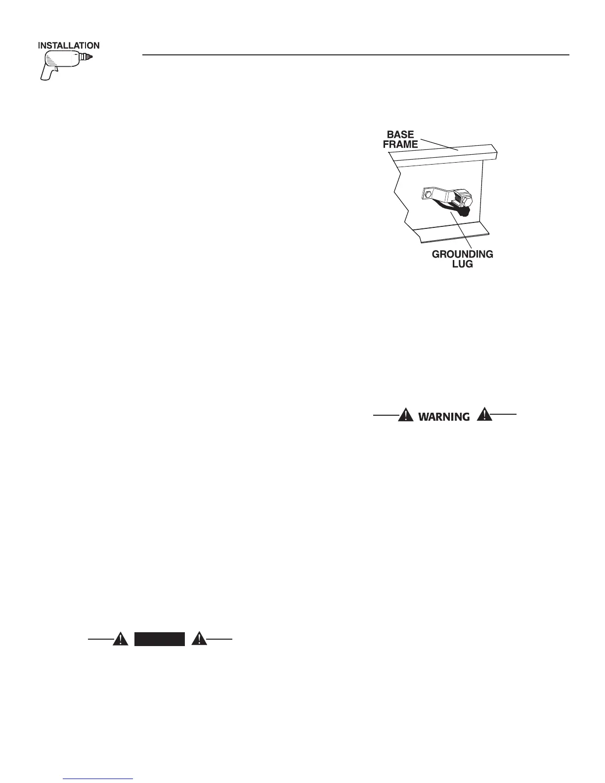
2.7 GROUNDING THE GENERATOR
The National Electrical Code requires the frame and
external electrically conductive parts of this equip-
ment to be properly connected to an approved earth
ground and/or grounding rods. For that purpose, a
GROUND LUG (Figure 2.2) is provided on the gen-
erator mounting base. Consult a qualified electrician
for grounding requirements in the area. Grounding
procedures must meet local regulations.
DANGER
Do not connect the ground wire to any pipe
that carries a flammable or explosive substance
– FIRE or an EXPLOSION may result.
Proper grounding helps protect personnel against elec-
trical shock in the event of a ground fault condition
in the generator or in connected electrical devices. In
addition, grounding helps dissipate static electricity
that often builds up in ungrounded devices.
Figure 2.2 – Generator Grounding Lug (typical)
2.8 GENERATOR AC NEUTRAL
CONNECTIONS
The manufacturer uses an UNGROUNDED AC neu-
tral. Grounding is recommended only at the main
service entrance. If the neutral wire is grounded and
one of the phase loads becomes grounded, the exces-
sive current opens the load circuit breaker or col-
lapses the generator field. The actual result depends
on the electrical characteristics of the particular
installed generator.
Failure to connect the generator neutral proper-
ly will result in unbalanced line-to-neutral volt-
ages. Resulting high voltages will cause equip-
ment damage.
2.9 USING A “GTS” TRANSFER
SWITCH
When required, the pre-packaged standby generator
can be installed with a “GTS” type engineered auto-
matic transfer switch.
In this application, the GTS transfer switch is
responsible for utility sensing, weekly exercising, and
load transferring.
Position two of the eight-position DIP switch is used
to turn over this control to the GTS.
In order for the battery charger to work, it is neces-
sary to provide a fused 240 VAC utility source to the
N1 and N2 terminals in the control panel.
Pos2 ON — GTS Application
• The control board will NOT monitor utility.
• The control board will NOT perform a weekly exer-
cise. (The five red LEDs will flash one at a time in
this mode.)
• The control board will NOT activate the transfer
output.
Section 2 — Installation
Liquid-cooled 25 kW Generators