0
0
18
18
44B
11A
T1
0
0
22
22
44C
0
22
44B
0
11C
22
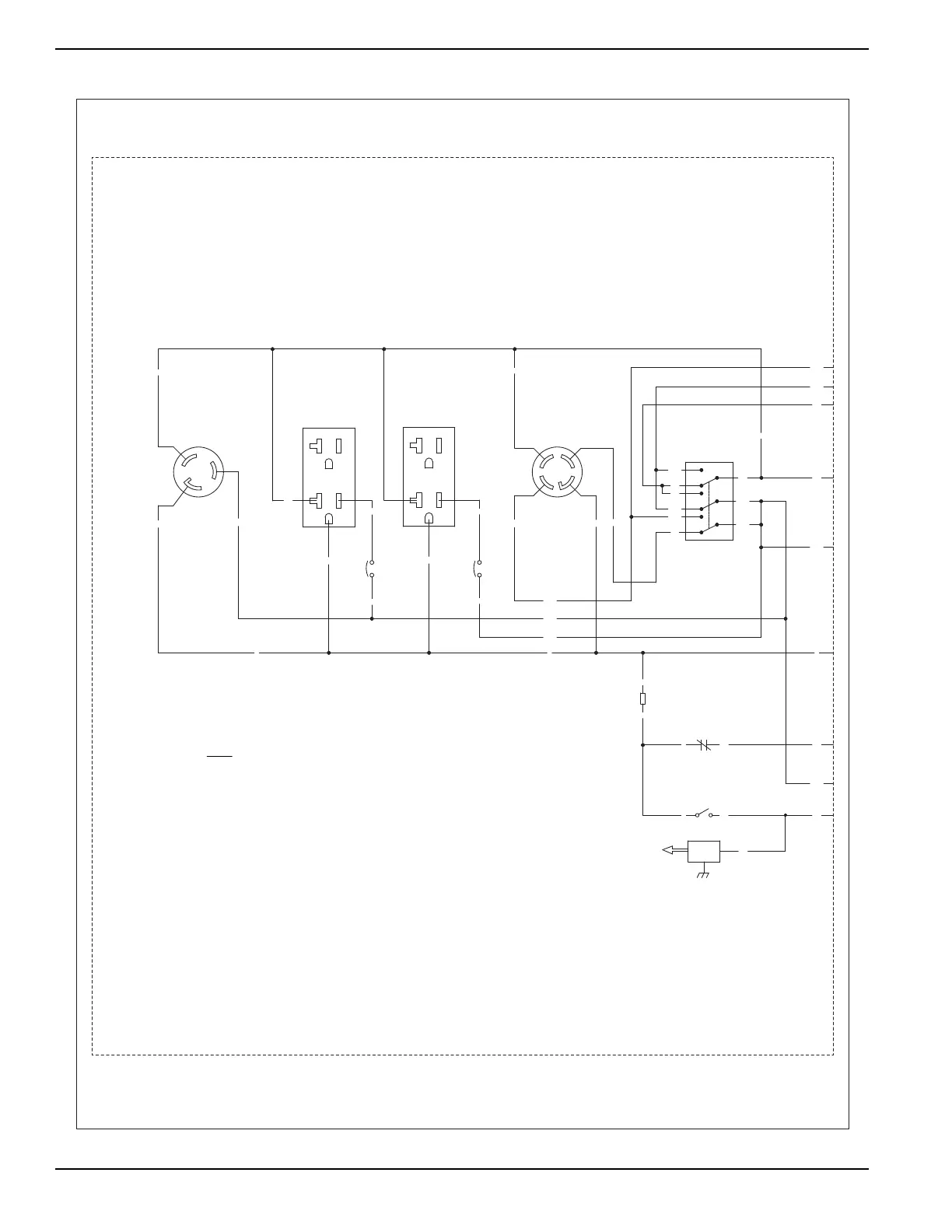
120V/20A
DUPLEX
120V/20A
22
DUPLEX
SP
IM
LOP
SW1
30A/3PDT
T1
22
33
33
33
44A
44A
11A
1
2
3
4
5
6
7
8
9
44A
11A
22
0
0
44B
11B
11A
44B
11B
22
8686
18
0
POSITION SHOWN
120V/240V
SW2
AVR - AUTOMATIC VOLTAGE REGULATOR
BA - BRUSH ASSEMBLY
C1 - 2 POS FREE HANGING CONNECTOR,
C2 - 4 POS AVR TO ALTERNATOR CONNECTOR,
NEUT - NEUTRAL STUD
ICT - IDLE CONTROL TRANSFORMER
GND - GROUND STUD
IM - IGNITION MODULE
LOP - LOW OIL PRESSURE SWITCH
120/240V, 30A, 3PDT
SW1 - VOLTAGE SELECTOR SWITCH,
SW2 - RUN-STOP SWITCH
HM - HOUR METER
SP - SPARK PLUG
LEGEND
PLUG TO CAP
CAP TO PLUG
0
0
( )
5-20R
5-20R
DPE - DISPLACED PHASE EXCITATION, 90°
20A/1P
C.B.
11B
G
X
WHT
Y
30A
TWISTLOCK
120V/240V
L14-30R
X
G
WHT
TWISTLOCK
120V
30A
L5-30R
20A/1P
C.B.
44B
11B
SCHEMATIC - DIAGRAM
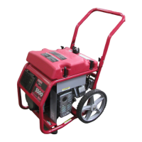
XP4000 PORTABLE
DRAWING #: 0H8536
REVISION: D
DATE: 05/20/11