Do you have a question about the Generac Power Systems SMM and is the answer not in the manual?
| Input Voltage | 120/240 VAC |
|---|---|
| Frequency | 60 Hz |
| Compatibility | Generac Generators |
| Phase | Single-phase |
| Operating Temperature Range | -4° to 140° F (-20° to 60° C) |
| Description | Generac Power Systems SMM is a control unit designed for monitoring and managing power systems. |
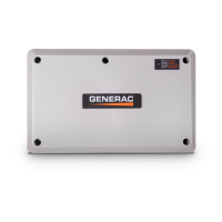
Overview of the Generac Smart Management Module (SMM) and its purpose in managing home standby generator loads.
Emphasizes the critical importance of reading and understanding the manual before operating the product to prevent injury.
Details safety alerts like DANGER, WARNING, CAUTION, and general safety precautions for safe operation.
Provides contact information for Generac Customer Service for assistance with servicing and repairs.
Highlights critical hazards such as electrocution, warning users to turn off power supplies before connecting lines.
Discusses options for load management systems, including Smart Management Modules (SMMs) and Smart A/C Modules (SACMs).
Covers factors influencing generator overload, load shedding logic, and priority settings for SMM usage.
Details the capabilities of the SMM, its self-contained nature, and accommodation of up to eight modules.
Identifies SMM features like Priority Dial, Lockout Switch, LED indicators, and items included in the carton.
Explains the procedure to enable lockout mode for non-essential loads during generator overload conditions.
Identifies and describes the function of jumpers on the SMM control board, including frequency and mode selection.
Lists key electrical parameters for the SMM, including input voltage, current rating, and motor rating.
Details the SMM enclosure type (NEMA 3R) and its operating temperature range for various environments.
Provides step-by-step instructions for opening the carton and verifying all SMM components are present.
Lists the essential tools needed for the proper installation of the Smart Management Module.
Offers guidance on selecting a mounting location and safely installing the SMM enclosure using provided holes.
Details the wiring diagram and procedures for connecting the SMM to power source and load lines.
Outlines the general process for testing the Smart Management Module after installation.
Describes the specific steps for conducting a utility power test to verify SMM operation and LED indicators.
Covers final installation tasks such as installing covers and placing priority decals for record-keeping.
Provides a comprehensive table listing common problems, their causes, and recommended correction procedures.
 Loading...