Installation, Tests, and Troubleshooting
10 Owner’s/Installation Manual for SMM
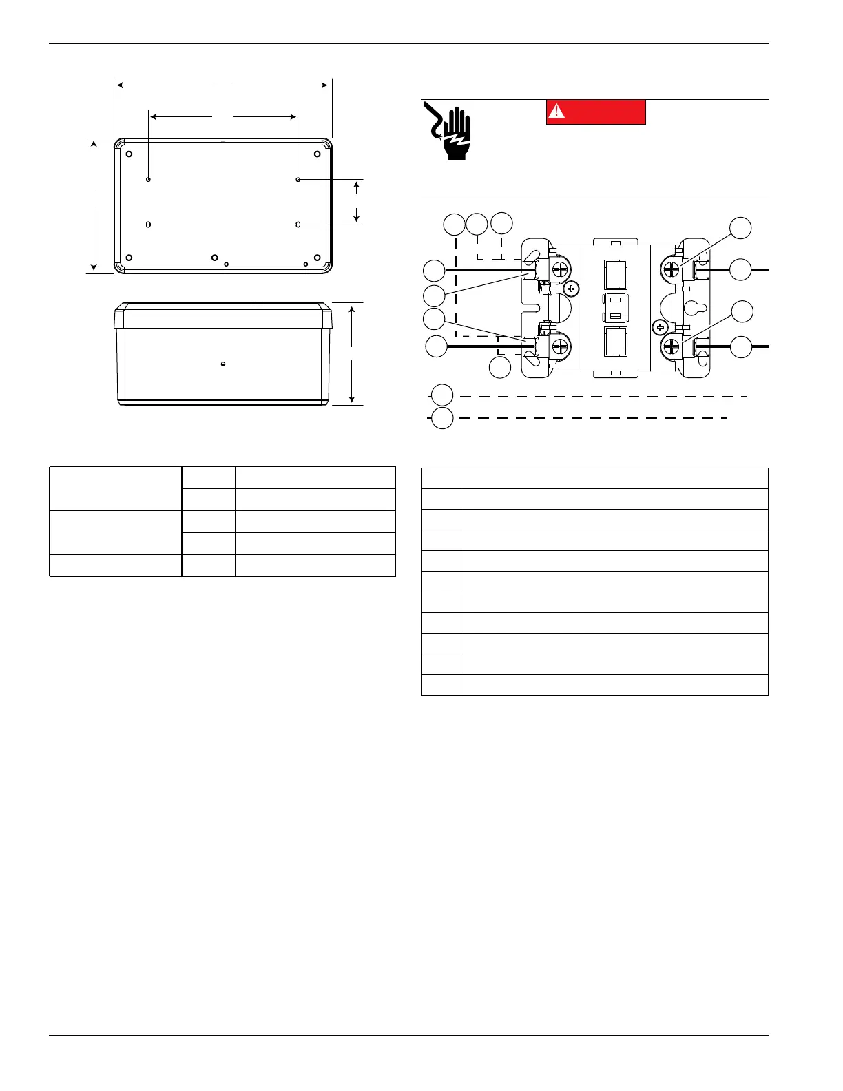
Figure 3-1. Mounting Dimensions
4. Install SMM enclosure to mounting surface using
appropriate mounting screws or wall anchors.
Connections
Figure 3-2. Wiring Diagram
1. Turn off both UTILITY (NORMAL) and EMER-
GENCY (STANDBY) power supplies before con-
necting power source and load lines to transfer
switch and SMM.
NOTE: Suitable conduit fittings must be installed in
knockout openings when running supply and load wires.
NOTE: Use at least 167 °F (75 °C) rated wire and gauge
per installation instructions. See Table 3-1 for recom-
mended wire size based on load current.
Height (in/mm)
H1 7.0 / 178.5
H2 2.4 / 61.0
Width (in/mm)
W1 11.4 / 289.4
W2 7.8 / 200.0
Depth (in/mm) D1 5.3 / 136.9
W1
W2
H2H1
D1
009113
Legend
A Red (240 VAC - Line)
B Black (240 VAC - Line)
C Red (240 VAC - Load)
D Black (240 VAC - Load)
E White - Neutral (as required)
F Green - Ground (as required)
G Black - Factory (PCB)
H Red - Factory (PCB)
I Blue - Factory (PCB)
J Blue - Factory (Jumper)
Electrocution. Turn utility and emergency
power supplies to OFF before connecting
power source and load lines. Failure to do so
will result in death or serious injury.
(000116)
DANGER
009377
T1
T2
A
B
C
D
E
F
H
G
J
L1
L2
I