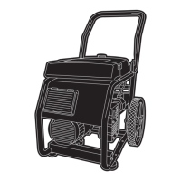
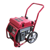
WheelHouse™ 5500 Watt Generator
7
OPERATING THE
GENERATOR
CAUTION! Never start or stop unit with
electrical loads connected AND with the connected
devices turned ON.
Starting the Engine
Disconnect all electrical loads from the generator. Follow
these start instruction steps in numerical order:
1. Make sure the fuel line quick connect is hooked up
and that all four tank hold-downs are firmly tight.
2. Turn the vent knob fully counter-clockwise. See
Figure 3 on page 5.
3. Rotate the fuel valve to the “On” position. See
Figure 4 on page 5.
4. Move the choke lever to the “Choke” position
(Figure 9).Your unit may appear slightly different from
that shown here.
5. Set the rocker switch to “On” position (Figure 10).
6. Grasp the recoil handle and pull slowly until slight
resistance is felt.Then pull rapidly to start engine.
7. Move choke lever to “Run” position a short distance at
a time over several seconds in warm weather or
minutes in cold weather. Let engine run smoothly before
each change. Operate with choke in “Run” position.
NOTE: If engine still fails to start after 3 pulls, check for
proper oil level in crankcase.This unit is equipped with a
low oil device that will not allow the engine to start. See
engine manual.
Refer to the engine owner’s manual for more
detailed starting instructions.
Connecting Electrical Loads
• Let engine stabilize and warm up for a few minutes after
starting.
• Plug in and turn on the desired 120 and/or 240 Volt AC,
single phase, 60 Hz electrical loads.
• Do Not connect 240 Volt loads to the 120 Volt
receptacles.
• Do Not connect 3–phase loads to the generator.
• Do Not connect 50 Hz loads to the generator.
• DO NOT OVERLOAD THE GENERATOR. See
“Don’t Overload the Generator” on page 9.
Stopping the Engine
• Unplug all electrical loads from generator panel
receptacles. Never start or stop engine with electrical
devices plugged in and turned on.
• Let engine run at no–load for 30 seconds to stabilize the
internal temperatures of engine and alternator.
• Move rocker switch to “Off”.
• Close the fuel shut–off valve.
Figure 10 — Rocker Switch
Figure 9 — Choke Lever
 Loading...