8
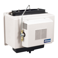
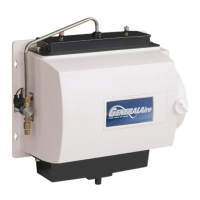
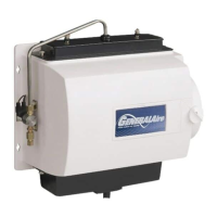
Model 1137 Humidier Installation Manual
Breathe Healthier! Residential Whole House Indoor Air Quality
Maintenance
Your Humidier is engineered to give helpful and trouble-free humidication. For maximum efciency the following
cleaning procedures should be carried out at the end of each heating season:
1. Turn off water supply and electrical power to humidier.
2. Remove water distributor tube, distributor trough, used Vapor Pad
®
and drain pan. The Vapor Pad
®
may be removed
from either the top or bottom of the humidier. Clean excessive mineral deposits from the distributor trough, drain
pan and humidier cabinet. A solution of 1/2 vinegar & 1/2 water will help loosen mineral deposits.
3. Insert a new 990-13 (GFI #7002) Vapor Pad
®
(black notch on top). Install trough and drain pan. Replace the
distributor tube to proper position over the distributor trough. Replace Vapor Pad
®
yearly for peak performance.
4. In heavy mineral areas, or if the solenoid valve fails to function, disconnect the 1/4” water supply line from the
solenoid valve. Remove the brass strainer body from the solenoid valve. Carefully pull the strainer screen 990-17
(GFI #7005) from the orice tting. Clean the mineral deposits from all parts. If the orice is clogged, it may be
opened by inserting a small needle. Reinsert the lter into the orice tting and screw the brass strainer body into
the solenoid valve.
5. Reconnect the 1/4” water line to the solenoid valve if necessary. Turn on the water supply and check all points for
leakage. The operation of the unit may be checked by starting the furnace. The humidier operates only when the
furnace blower is running or the burner circuit is energized. The humidier is now ready for operation.
6. During the summer, turn off water supply and electrical power to humidier. Close air damper.
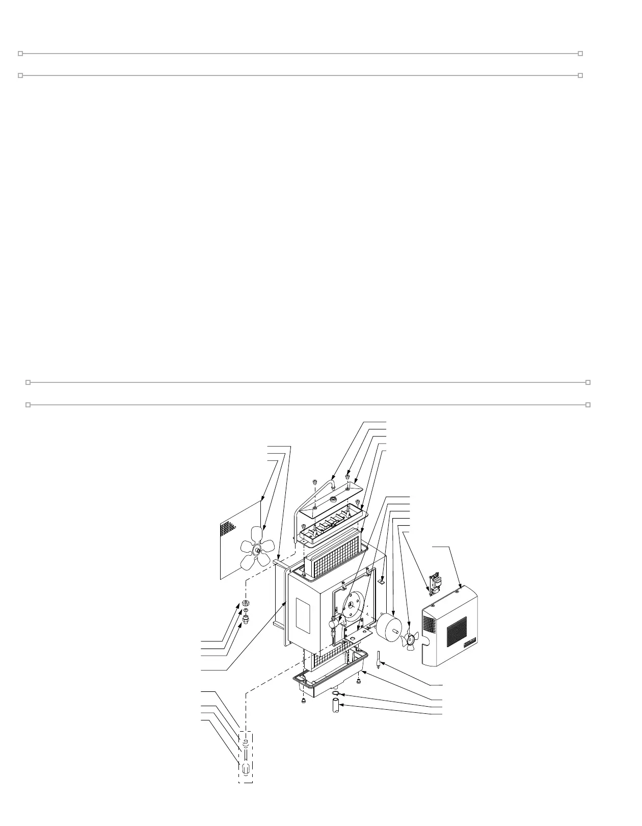
Parts Drawing
SOLENOIDVALVE
ASS'Y 990-53
1137-7 WIRING BRACKET
40-7 TINNERMAN NUT
1137-8 MOTOR
1137-50 COOLING FAN
GA4238 RELAY ASS'Y (FORMERLY 1137-26)
1137-39 FRONT COVER
ASS'Y
1137-3 DRAIN PAN
P-163 HOSE CLAMP
1099-16 DRAINTUBE
P-103 COMPRESSION NUT
P-104 COMPRESSION SLEEVE
P-111 CONNECTOR
1137-38 CABINET ASSEMBLY
990-37-76 ORIFICE & STRAINER
ASSEMBLY
990-16-76 ORIFICE FITTING
990-17 STRAINER SCREEN
990-18 STRAINER BODY
1137-2 FAN SHROUD
1137-9 FAN BLADE
1137-20FAN GUARD
1137-24 DISTRIBUTOR TUBE
1099-9 THUMB NUT
1137-35 TROUGH COVER
1137-4 DISTRIBUTOR TROUGH
990-13 EVAPORATOR PAD
1137-31 POWER SUPPLY CORD