Version: 2020-09-04
87
Copyright of the European Union is effective (Copyright EU) (c) 2019 GENEREX Systems GmbH, Hamburg, Germany, All rights reserved
TEL +49(40)22692910 - EMAIL generex@generex.de - WEB www.generex.de (This and all other product datasheets are available for download.)
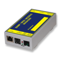
SENSORMANAGER
The SENSOR MANAGER is an optional accessory to extend the functionality of the CS141:
The GENEREX sensors / actuators can easily be connected to the SENSOR MANAGER, required RJ12 connection cables are included
on delivery. The sensor can be configured via the web interface of the CS141 / BACSWEBMANAGER. Any third-party sensor or
actuator that are conform with required specifications, can be used with the SENSORMANAGER.
SENSORMANAGER_II application examples:
Monitoring of sensor data
Temperature, humidity, electr.. Electricity, electr. Voltage, electr. performance and other analogue measurements.
Monitoring of contacts:
Door contacts, fire detectors, motion detectors, water detectors, glass breakage sensors and other potential-free signaling contacts.
Switching:
Switching of optical and acoustic actuators such as flashing lights, warning horns u. relay contacts
SENSORMANAGER_II input signals:
Up to 8 analog inputs (0-10VDC o. 0 / 4-20mA)
Up to 4 digital inputs (potential-free contacts)
SENSORMANAGER_II output signals:
Up to 4 digital output signals (open collector / 12VDC max 30mA)
SENSORMANANAGER_II PIN assignment of the Rj12 connection sockets
INPUT 1:
Pin 1 9-24VDC, output according to input of supply voltage, default delivery: 12VDC power supply
Pin 2 Analog input channel 1 (0-10VDC o. 0/4-20mA)
Pin 3 Analog input channel 2 (0-10VDC o. 0/4-20mA)
Pin 4 Ground (GND)
Pin 5 Digital output (Open-Collector 9-24VDC/max. 30mA, Default on delivery: 12VDC)
Pin 6 Digital input (min./max. 9-24V via Pin 1)
INPUT 2:
Pin 1 9-24VDC, output according to input of supply voltage, default delivery: 12VDC power supply
Pin 2 Analog input channel 3 (0-10VDC o. 0/4-20mA)
Pin 3 Analog input channel 4 (0-10VDC o. 0/4-20mA)
Pin 4 Ground (GND)
Pin 5 Digital output (Open-Collector 9-24VDC/max. 30mA, Default on delivery: 12VDC)
Pin 6 Digital output (min./max. 9-24V via Pin 1)
INPUT 3:
Pin 1 9-24VDC, output according to input of supply voltage, default delivery: 12VDC power supply
Pin 2 Analog input channel 5 (0-10VDC o. 0/4-20mA)
Pin 3 Analog input channel 6 (0-10VDC o. 0/4-20mA)
Pin 4 Ground (GND)
Pin 5 Digital output (Open-Collector 9-24VDC/max. 30mA, default on delivery: 12VDC)
Pin 6 Digital input (min./max. 9-24V via Pin 1)
INPUT 4:
Pin 1 9-24VDC, output according to input of supply voltage, default delivery: 12VDC power supply
Pin 2 Analog input channel 7 (0-10VDC o. 0/4-20mA)
Pin 3 Analog input channel 8 (0-10VDC o. 0/4-20mA)
Pin 4 Masse (GND)
Pin 5 Digital output (Open-Collector 9-24VDC/max. 30mA, Default on delivery: 12VDC)
Pin 6 Digital input (min./max. 9-24V via Pin 1)
 Loading...