Version: 2020-09-04
90
Copyright of the European Union is effective (Copyright EU) (c) 2019 GENEREX Systems GmbH, Hamburg, Germany, All rights reserved
TEL +49(40)22692910 - EMAIL generex@generex.de - WEB www.generex.de (This and all other product datasheets are available for download.)
SENSORMANAGER II: Available sensors
These sensors are currently available for SENSORMANAGER_II:
GENEREX-Analog-Sensors:
SM_T (Temperature sensor -> 1 analog channel required)
SM_T_H (Combined sensor: Temperature and humidity -> 2 analog channels required)
SM_VMC (True RMS AC voltage sensor -> 1 analog channel required
SM_CSxxxA (AC- current sensor -> 1 analog channel required)
GENEREX-Digital-Input-Sensors
SM_HYG2 (water and humidity sensor -> 1 digital input required)
SM_Glas (Glas breach detector -> 1 digital input required)
SM_MD (motion detector -> 1 digital input required)
SM_SD (Smoke - und fire dector -> 1 digital input required)
SM_DC (door contact alarm detector -> 1 digital input required)
SM_H2 (Hydrogen Sensor -> 2 digital inputs required)
Digital GENEREX-Actuators:
SM_IO (Ralais-Box -> 1 digital output required)
SM_BUZ (accustical alarm buzzer -> 1 digital output required)
SM_Flash (flash light -> 1 digital output required)
SENSORMANAGER_II – Installation and configuration
Before you start …
The configuration must be saved to the PIC processor of the SENSOR MANAGER. This will be done by the CS141 automatically if
pressing save buttons. If a configured SENSOR MANAGER needs to be replaced, the configuration stored in the CS141 must be written
to the new PIC processor by applying again. A spare parted SENSORMANAGER will not work without writing the new configuration.
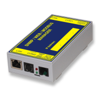
SENSORMANAGER_II: Connecting to CS141
Use the supplied cable to connect the COM1 of the SENSOR MANAGER II to the COM 2 of the CS141.
Log into the CS141 and go to general COM port settings. Configure the comport for sensormanager
usage.
Then connect the power supply to the SENSORMANAGER:
Two LED's are installed on the underside of the SENSOR MANAGER: one should now light continuously
and signal the operational readiness. The second LED flashes only when the CS141 makes a request to
the SENSORMANAGER.
After the SENSORMANAGER is ready for configuration, open sensor manager configuration menu at CS141 and start configurating
your sensors and devices.
Note:
The CS141 will only make a request to the SENSORMANAGER if it is configured accordingly. The LED on the sensor manager will only
flash when a request has been received or is answered by the SENSORMANAGER.
Please note that the sensor manager is a stand-alone device with its own power supply. In case of main power supply is not available
will cause disabling the connected sensors and actuators. The CS141 will notice this fact and can be configured to send custom alarm
messages for sensor lost issues.
When using a SENSORMANAGER, ensure both, CS141 and SENSORMANAGER are secured by independent power supply (UPS) for
full operationality in case of main power issues.
 Loading...