Ver 1.0
9
~ÄëçäìíÉ=ÑáÇÉäáíó
that it will drive. The Control Module is stacked on top of the two
Servo-Amplifier Modules and the entire stack is on an amplifier
acoustic suspension system. Two Power Transformers are placed
behind each stack.
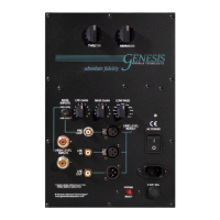
Next, using the supplied 7-pin Control Interface Cables, link the
Control Module to each Servo-Amplifier Module. Plug the included
IEC power cord into the Control Module.
1.4 Power Connections
Each amplifier module is powered by a separate external Power
Transformer. By having the power transformer external to the
electronics, and potential vibration or electromagnetic interference is
isolated from the sensitive low-voltage electronics.
When you make the power connections, pay close attention to the
way the connector works. This connector is a 20 amp twist-lock
Neutrik™ PowerCon™. By looking carefully, it will be obvious as to
how it works. It only goes in one way and you cannot put it in wrong.
However, you can fail to put it in all the way. Line up the alignment
pins on the connectors, push the plug in, and twist it clockwise until
the lock "clicks" in place to keep it there.
To remove the connector, pull the silver locking tab outwards, twist it
anti-clockwise, and pull out.
The Neutrik™ PowerCon™ 20 amp connectors used are the best
solution we have found for passing power, but they are not designed
to make/break connections. Hence, it is important that they are
connected before supplying power to the Power Transformers.
Use the included Power Umbilicals to connect between the Amplifier
Modules and the Power Transformers. Next, plug the included IEC
power cord into the Power Transformer. Leave it unplugged from the
wall outlet until you have all the rest of the connections completed.
1.5 Woofer Connections
Included with your Genesis 1.2 is a set of four large cables (with 3
channels each) used to connect the woofer towers to the Servo-
Amplifier Modules. Each end of the cable is clearly marked, AMPLIFIER
or
SPEAKER. It does not matter which connector is attached to which
input or output as long as the correct amplifier modules are used for
the left and right towers. It also does not matter which SBC is used for
the left or the right; however, one pair is marked with
AMPLIFIER or
SPEAKER in red lettering, and the other in white lettering for