We thank you for having chosen one of our products. FAAC is
certain that from it you will obtain all the performance you require.
All our products are the result of years of experience in the eld
automated systems, with the added advantage of being part of
one of the sector’s leading groups.
Inside the manual you will nd a detachable booklet
containing all the images for installation.
IMPORTANT NOTES FOR THE INSTALLER
• Before beginning installation of the operator, carefully read the
entire manual.
• Keep this manual for future reference.
•
Correct operation and the declared technical specications are
obtained only by complying with the instructions contained in
this manual and using FAAC accessories and safety devices.
•
If a mechanical clutch device is not available, use a control unit
featuring an adjustable electronic clutch.
•
This automated system has been designed and built for
controlling vehicle access. Avoid any different use.
•
The operator must not be used to control emergency exits or
gates installed on emergency lanes (escape routes).
•
If the leaf you wish to motorise features a built-in door for
pedestrian passage, the door must be equipped with a safety
switch in order to disable operation of the gate when the door
is open.
• Do not pass while the gate is moving.
•
Whatever is not explicitly provided for in these instructions is to
be considered strictly forbidden.
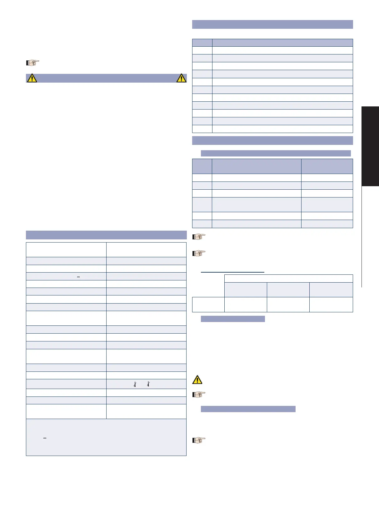
TECHNICAL SPECIFICATIONS
System power supply
a
230V~ 50Hz
115V~ 60Hz
Motor power supply 24V
"
Max. absorbed power (W) 140
Max. torque at 24V (Nm) 220
Nominal torque (Nm) 130
Opening angle (°) 180
Angular speed (°/sec.)
b
6
Max leaf weight (Kg) See chart in g. 2
Max leaf length (m)
1.8
2.5 (with electronic lock)
Usage type Residential
Max consecutive cycles
c
30
Daily cycles
c
50
Max continuous operating
time
O.T. 17 min.
Protection class IP67
Noise dB(A) <70
Operating temperature (°C)
-20 +55
Operator weight (Kg) 6.5
Operator dimensions (mm) 311x168 H120
Supporting box dimensions
(mm)
See gure 3
a
Depending on the paired control unit.
b
Value derived from laboratory tests with the engine running at
24V without load. The angular velocity of the leaf can vary
according to the weight of the leaf and the power supply
c
Values obtained from laboratory testing.
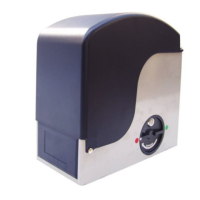
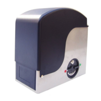
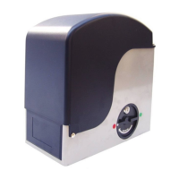
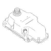
DESCRIPTION OF THE COMPONENTS
With reference to Fig. 1
Pos Description
a
Supporting box
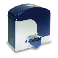
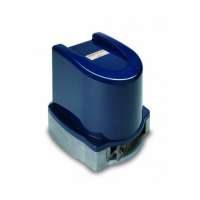
b
Operator
c
Gate support frame
d
Locking frame
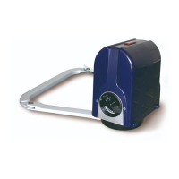
e
Release device
f
Cable runner
g
Draining hole
h
Lubrication hole
i
Drive pinion
j
Closing cover
k
Plug
INSTALLATION
Electrical preparations (standard system) Fig. 4.
Pos Description
Cable nr.
and diam.
a
Gearmotor 2 x See table
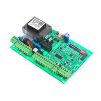
b
Control unit (system power supply)
3x1.5mm
2
c
TX Photocells 2x0.5mm
2
d
RX Photocells
4x0.5mm
2
2x0.5mm
2
(BUS)
e
Key selector 2x0.5mm
2
f
Flashing lamp 2x1.5mm
2
For cable installation, use adequate rigid and/or exible
tubes.
Separate the 230/115V~power cables from the low-voltage
ones.
motor cable diameter
Operator - Board distance
Up to 15 m
From 15 m to
25 m
From 25 m
to 35 m
Conductor
diameter
2.5 mm
2
4 mm
2
6 mm
2
Preliminary checks
1. The mechanical elements used for construction must comply
with EN 12604 and EN 12605 Standards.
2. The leaf structure must be suitable for automation.
3.
Minimum distance between the lower edge of the leaf and the
oor as shown in g. 5.
4. Presence of mechanical leaf limit stops.
5. Check for the presence of only the upper hinge.
The condition of the structure directly affects the
reliabilityandsafetyoftheautomatedsystem.
Before installing the automated system, carry out any
necessary smith work on the gate
Walling in the supporting box
1.
Choose the orientation of the box according to the dimensions
shown in g. 6 and 7.
2. Dig a hole for positioning the box, g. 8.
Modify the dimensions of the hole according to the type
of ground (the dimension in gure 8 refer to the minimum
dimensions of the hole).
3. Position the box as shown in g. 9.
4.
Place a rigid tube or a exible sheath for passage of the power
supply cables, g. 10 ref a.
5. Place a tube for draining rain water, g. 10 ref. b.
6. Ensure that the box is walled-in at.
7 00058I0941 - Rev.3DIABLO
Translation of the original instructions
ENGLISH
 Loading...