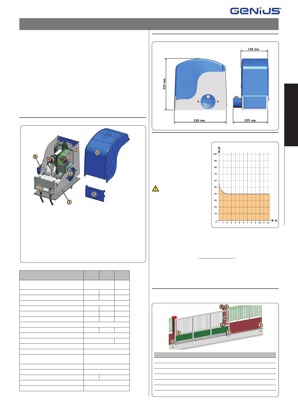
2. DIMENSIONS
3. MAXIMUM USE CURVE
The curve makes it possible to
establish maximum work time (T)
according to use frequency (F).
With reference to standard IEC
34-1, the FALCON gearmotor, with
service type S3, can operate at use
frequency of 40%.
To ensure efficient operation, op-
erate in the work range under the
curve.
Important: The curve is ob-
tained at a temperature of
20°C. Exposure to the direct
sun rays can reduce use
frequency down to 20%.
Calculation of use frequency
The percentage of effective work time (opening + closing) compared to
total time of cycle (opening + closing + pause times).
Calculation formula:
Ta + Tc
% F = X 100
Ta + Tc + Tp + Ti
where:
Ta = opening time
Tc = closing time
Tp = pause time
Ti = interval time between one complete cycle and another
4. ELECTRONIC DEVICES (standard system)
FALCON AUTOMATED SYSTEM
These instructions apply to the following models:
FALCON 14 M - FALCON 14 MC - FALCON 20 M- FALCON 20 MC - FALCON
15 M - FALCON 15 MC
The FALCON gearmotor for sliding gates is an electro-mechanical operator
which transmits drive to the sliding leaf by a rack and pinion or by a chain
suitably coupled to the gate.
The non-reversing system guarantees mechanical locking of the gate when
the motor is not operating and, therefore, there is no need to install any lock.
The gearmotor does not have a mechanical clutch and, therefore, requires
a control unit with an adjustable electronic clutch which guarantees the
necessary anti-crushing safety.
A handy manual release with a customised key makes the gate manoeu-
vrable in case of a power cut or trouble.
In the “C” version gearmotors, the electronic control unit is housed inside
the operator.
The FALCON gearmotor was designed and built for controlling vehicle access.
Do not use in any different way.
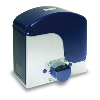
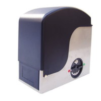
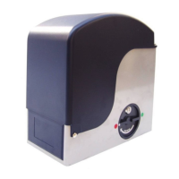
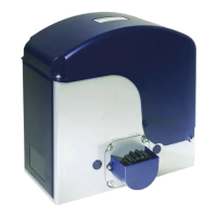
1. DESCRIPTION AND TECHNICAL SPECIFICATIONS
Foundation plate
Gearmotor
Enclosure and control unit
(In “C” versions only)
Magnetic sensor
Pinion
Release knob with key
Securing slots and nuts
Lateral protective devices
Covering housing
Pos. Description Connection cable
Gearmotor 3x2.5 mm
2
(230/115V~)
Photocell transmitter 2x0.5 mm
2
(TX)
Photocell receiver 4x0.5 mm
2
(RX)
Key-operated selector switch 2x0.5 mm
2
Flashing light 2x1.5 mm
2
External receiver (optional) 3x0.5 mm
2
MODEL
14 M
14 MC
20 M
20 MC
15 M
15 MC
Power supply (+6% -10%)
230 V~
50 Hz
115 V~
60 Hz
Absorbed power (W) 650 800 710
Absorbed current (A) 2.8 3.5 6.7
Electric motor (rpm) 1400 1700
Thrust capacitor (μF) 16 20 60
Thrust on pinion (daN) 110 150 130
Torque (Nm) 35 45 38
Temperature protection (°C) 140
Max leaf weight (Kg) 1400 2000 1500
Type of pinion gear Z 16 module 4
Gate speed (m/min) 10 11
Max. gate length (m) 20
Type of travel-limit device Magnetic
Type of clutch
Electronic torque control
(See control unit)
Use frequency (see graph) S3 - 40%
Operating ambient temperature (°C) -20 ÷ +55
Weight of gearmotor (Kg) 14 15
Protection class IP 44
Operator dimensions See fig. 2
Fig. 1
Fig. 2
Fig. 3
FALCON M 7 00058I0616 - Rev.1FALCON M 7 00058I0616 - Rev.1
Translation of the original instructions
ENGLISH
 Loading...