ENGLISH
15
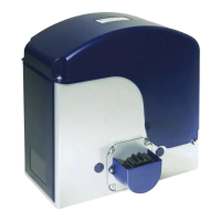
9)Close the leaf and, keeping the operator in a
perfect horizontal position, determine the
fastening point of the front bracket (Fig.12).
10) Temporarily fix the front bracket with two welding
spots (Fig.12).
Note: if the gate structure does not allow a fix bracket
fastening it is necessary to create a sturdy
supporting base in the gate structure.
11)Release the operator (see paragraph 6) and
manually check if the gate can completely open
without hindrances and stop at the mechanical
travel stops as well as if the leaf moves regularly
without any friction.
12) Carry out the necessary corrective measures
and repeat from point 8.
13) Temporarily release the operator from the front
bracket and weld the bracket definitively.
If the leaf structure does not allow a bracket
welding, the suitable bracket to screw (optional)
can be used together with suitable fastening
systems (Fig.13). Then carry out the same
operations as prescribed for the bracket to weld
Note: we recommend to grease all the fastening pins of the fittings.
4.5. Wiring the operator
A terminal board is fitted in the lower part of the operator for the connection of the motor, of any limit switch
and for the earthing of the operator.
IMPORTANT : To connect the motor, the supplied cable must be used for the mobile section, or a cable for
mobile laying from the outside.
Motor wiring operations:
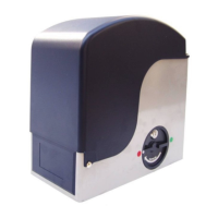
1) Open one of the two pre-drilled holes in the supplied cover, Fig.14; in case of operators with limit switches,
open both holes.
2) Fit the supplied cable gland.
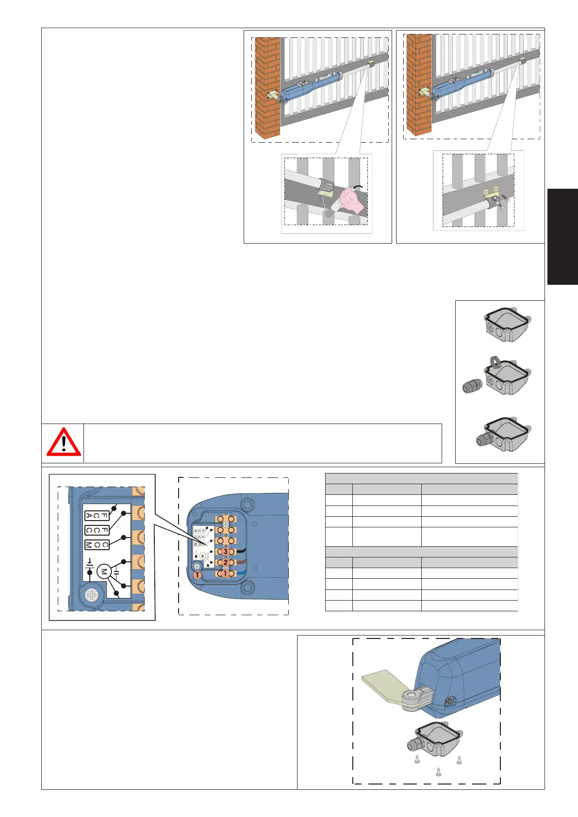
3) Connect the motor and the earthing with reference to Fig.15 and to the table.
4) Close the cover with the four supplied screws, Fig.16.
)~V511(~V032LARTSIM
.SOP RUOLOC NOITPIRCSED
1 )etihW(eulBelbacnommoC
2 )deR(nworB1esahP
3 )kcalB(kcalB2esahP
T
neerG/wolleY
)neerG(
gnihtraE
cdV42LARTSIM
.SOP RUOLOC NOITPIRCSED
1 eulB1esahP
2 desutoN/
3 nworB2esahP
T desutoN/
To maintain approval for CSA-UL approved operators, position the capacitor (secured in a
stable manner) inside a CSA-UL approved enclosure.
Fig. 12
Fig. 13
Fig. 14
Fig. 15
Fig. 16
 Loading...