ENGLISH
16
4.6. Limit switches
“LS” models are equipped with opening and closing limit switches. Therefore they require the use of a control board able to control
these inputs.
Note: Limit switches are triggered for the first and the last 30 mm of the travel. Therefore the operator should use the whole available
travel during the opening phase. Shorter travels can limit or completely cancel the limit switch adjustment range.
4.6.1. Wiring the limit switches
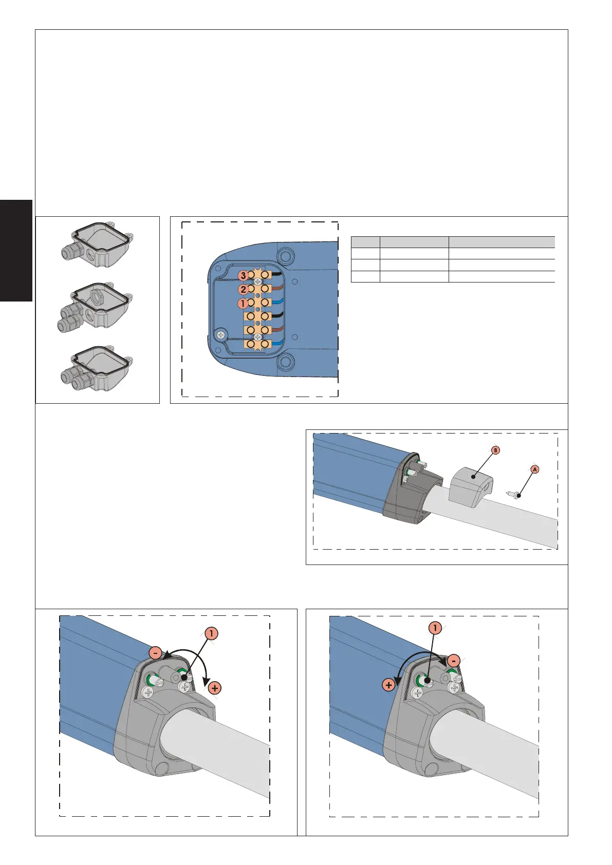
Limit switches are wired in the same terminal board where the motor wiring has been carried out. Wire the limit switches as follows:
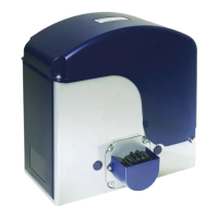
1) Open the second pre-drilled hole in the cover, Fig.17.
2) Fit the supplied cable gland, Fig.17
3) Insert the cable and connect it to the terminals observing the colours specified in the table of Fig.18.
4) Close the cover with the four supplied screws.
Note:
• For limit switches connection use the cable for the external movable laying with wires having a cross section of 0.5 mm2.
• During the wiring operations, observe the wire colours as specified in the table of Fig.18.
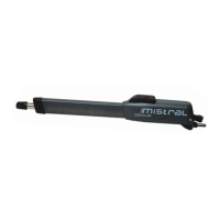
4.6.2. Adjusting limit switches
Limit switches adjustment is carried out as follows:
1) Unscrew the upper fastening screw, Fig.19 ref.A, and remove
the cap, Fig.19 ref.B.
2) To adjust the closing limit switch FCC turn the adjusting screw
clockwise, Fig.20 ref.1, to increase the rod stroke and counter-
clockwise to reduce it.
3) To adjust the opening limit switch FCA turn the adjusting screw
counter-clockwise, Fig.21 ref.1, to increase the rod stroke and
clockwise to reduce it.
4) Perform a pair of test cycles to check the correct position of
the limit switch. If the limit switches adjustment needs to be
carried out again, repeat the operation starting from point 2.
5) Riposition the cap, Fig.19 ref.B, and tighten the fastening screw
again, Fig.19 ref.A.
.SOP RUOLOC NOITPIRCSED
1 eulBelbacnommoC
2 nworB)CCF(hctiwstimilgnisolC
3 kcalB)ACF(hctiwstimilgninepO
Fig. 17
Fig. 18
Fig. 19
Fig. 20
Fig. 21
 Loading...