Panel installation
The Nano panel is supplied fully assembled, it is important to check the contents to ensure all the parts are supplied.
Note the 2 x 12V 7Ah batteries are supplied in a separate pack.
Parts in the Spares packages Quantity
Fuse T3.15A H 250V 20mm x 5mm Ceramic 1
Fuse T250mA H 250V 20mm x 5mm Ceramic 3
Fuse T1A TE5 2
Fuse 3,15A TE5 1
10K Ohms Resistor 4
Battery Link 1
Battery Lead 1
Allen Key# 1
Screw cover 1
Panasonic CR2032 3V cell 1
Trimmer tool 1
Document pack : Operating, Installation, Quick reference +
template and Log book
1
# - part supplied in a plastic bag fitted to the enclosure.
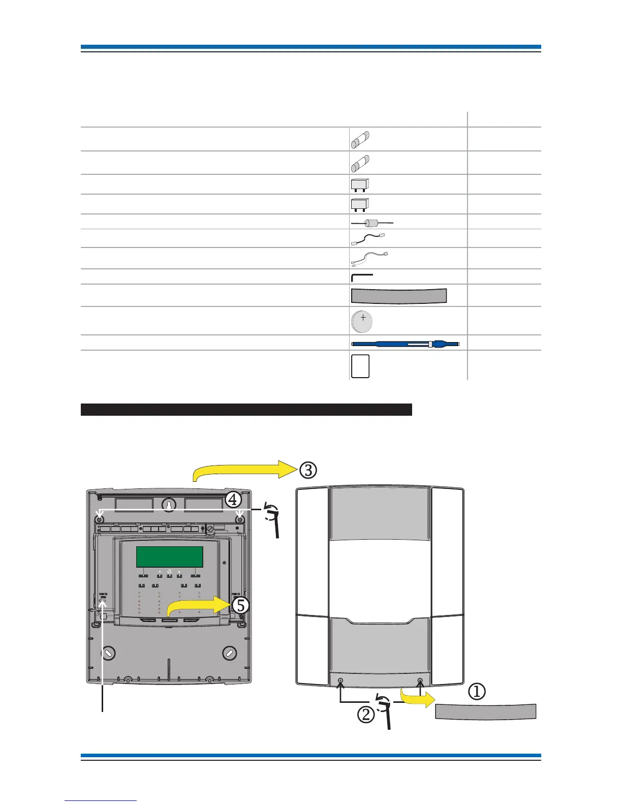
How to disassemble the panel to gain access to the Backbox
a
Pull out the 'screw cover' j which may be supplied fitted to the Outer Cover, the 'screw cover' is held in place by magnets.
b
Open the two captive screws k on the 'Outer cover' using the allen key and unhook the 'outer cover' l from the 'backbox'.
c
Open the two captive screws m on the 'electronic module' and lift out the module n from the 'backbox'.
Installation instructions
CR2032
3V
i
POWERFAULT
FIRE
Tes t
Delay
Verify
Sounder Fault
Zone 2
Zone 6
Zone 10
Zone 14
Zone 3
Zone 7
Zone 11
Zone 15
Zone 4
Zone 8
Zone 12
Zone 16
Disablement
Zone 1
Zone 5
Zone 9
Zone 13
System Fault
Sound
Alarms
Silence
Alarms
Power Fault
Reset
Cancel
Buzzer
Sounder
Disablement
Outer Cover
Allen Key
Electronic module
Backbox
Screw cover
Allen Key
 Loading...