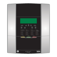
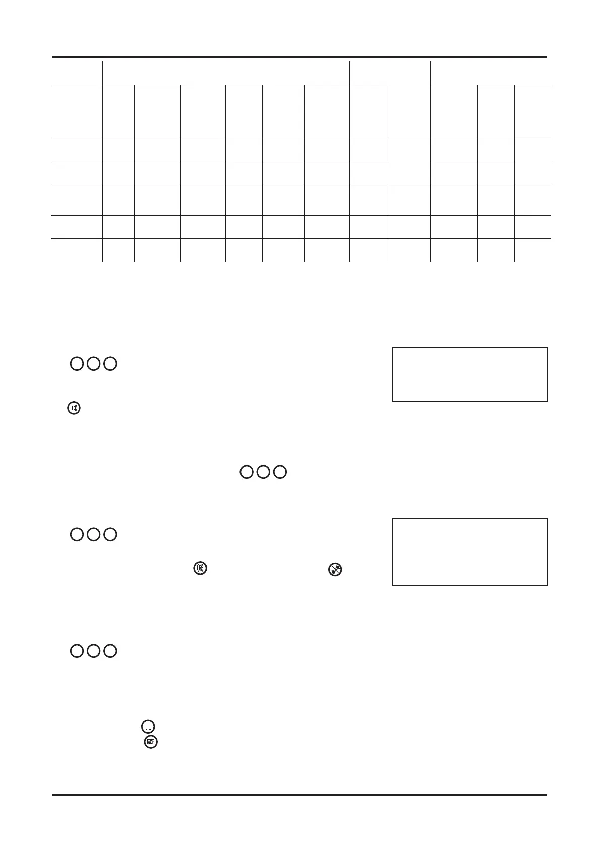
To Sound Alarms
To re-sound the alarm sounders
during a fire condition:
a)
Enter the 3 digit code
to gain access to
the controls.
b)
Press the Sound Alarms
button.
Notice the system alarm
Sounders are activated.
To Silence Alarms
To silence system alarm sounders
after they have been actuated:
a)
Enter the 3 digit code
to gain access to
the controls.
b)
Press the Silence Alarms
button.
Notice the system alarm
Sounders are silenced.
To carry out a display test
a)
#Enter the 3 digit code
to gain access to
the controls.
# Coded entry is only
required if Display test function
is configured for operation at
Access level 2.
b)
Press the ‘shift‘ button and
then the display button.
Ensure that all the LEDs light in
sequence and the buzzer
sounds.
Fault Condition
In the event of an automatic fault
detection the indications given are:
q Fault light is lit
q fault indicators are lit
q buzzer sounds intermittent.
(except for system fault which is
a continuous sound)
To Cancel fault buzzer
a)
#Enter the 3 digit code
to gain access to
the controls.
# Coded entry is only
required if Cancel Buzzer
function is configured for
operation at Access level 2.
b)b) After investigating fault, press
the Cancel Buzzer
button. Notice the buzzer is
silenced but other indications
remain active.
The fault indications are
normally automatically
extinguished once the fault
condition has been rectified.
Action to rectify fault
Suggested action to rectify fault
condition:
NOTE: All fault rectification work
must be done by suitably
qualified personnel.
The fault indicators may be
extinguished during a fire
condition.
The mains failure condition
overrides all other fault indications
in order to preserve battery
standby capacity.
NOTE: A comprehensive fault
finding guide is included in the
Installation and Commissioning
guide.
Operating instructions Fire Panels
03/01 6 Part 2 of 4188-424 Issue 2
v
v
n n n
n n n
n n n
n n n
Visual indications Audible
indication
Signals out
Condition Zone
Fire
(1-8)
-Red
Fire
Common
- Red
Disabled
- Yellow
Test -
Yellow
Power -
Green
Access/
Function
- Yellow
Buzzer Sounder
circuits
Aux
Relay
contacts
Normally
de-
energised
Comm
on
fault
-
Norma
lly
active
Comm
on fire-
Norma
lly
deacti
ve
Normal
indication
On Normal Active Deact
ive
Fire On On On On On Change
over
Active Active
New fire
(different
zone)
On On On On On Change
over
Active Active
AL2, 3 or 4 On On Normal Active Deact
ive
Function
key press
On Fast
Pulse
Normal Active Deact
ive
Indications on panel
http://www.firealarmengineers.com


 To Next Page
 Loading...