Further Information
Please refer to the user manual and our website:
www.greenenergyoptions.co.uk/our-products/solopv
MAN-SO-004
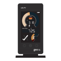
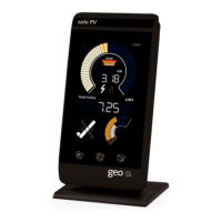
Solo PV Display
Installation Guide
Safety notice
It is important to observe some simple safety precautions
when using this product. Please read this important
information before continuing. Safe operation of the
Solo is impaired if used in a manner not specified by the
manufacturer.
The Solo product is designed to be installed simply and
without the need for a qualified electrical installer. There
is no need to open fuse boxes or to connect or disconnect
any cabling. It is designed to be used inside a suitable
building or meter cabinet.
Do not fit rechargeable batteries.
For use in dry environments only.
To protect the environment, this product and batteries
must be disposed of safely at the end of their life. Please
take to a recycling centre for safe disposal.
Keep the Solo away from water and other liquids.
Disconnect before cleaning and do not immerse in water
or other liquids. Please contact Green Energy Options if
any components appear damaged or faulty.
Troubleshooting
• Is the on, but the Display is showing
Please refer back to Step 3 – LED Reader
and Transmitter, checking with a light
source that the connection between the
LED Reader and Display is ok.
• Is the flashing?
This means that the Transmitter is out of
range. Please move the Display closer to
the Transmitter.
• Is the still flashing or not showing?
Please follow the steps below:
1. Unplug the LED reader from the
Transmitter, bring the Transmitter to
the Display.
2. Remove the cover from the Transmitter
and take out one battery.
3. With the Display on the main screen
press and hold the Pairing button on the
back of the Display until the message ‘NET
LEFT’ appears (the illustration below
shows where the button is).
4. Press the middle (set) button to return to
the main screen.
5. Press the Pairing button on the back of the
Display for one second so that ‘PAIRING’
is displayed.
6. Press and hold the Pairing button on the
Transmitter and whilst holding it:
6a. Replace the battery.
6b. Wait for the green light to show on
the Transmitter next to the Pairing button.
7. When the green light comes on, release
the Pairing button then replace the cover
of the Transmitter and reconnect the
LED reader.
8. The Display will now be showing ‘Paired’.
9. Press the middle button on the Display
to view the main screen. The should now
be on.
MAC : 00 00BC00 0B0 1 0 DA0
SN : 000000000 000 00
MAC : 00 00BC00 0B0 1 0 DA0
SN : 000000000 000 00
6
3
?
GreenEnergyOptions