Introduction
7
1
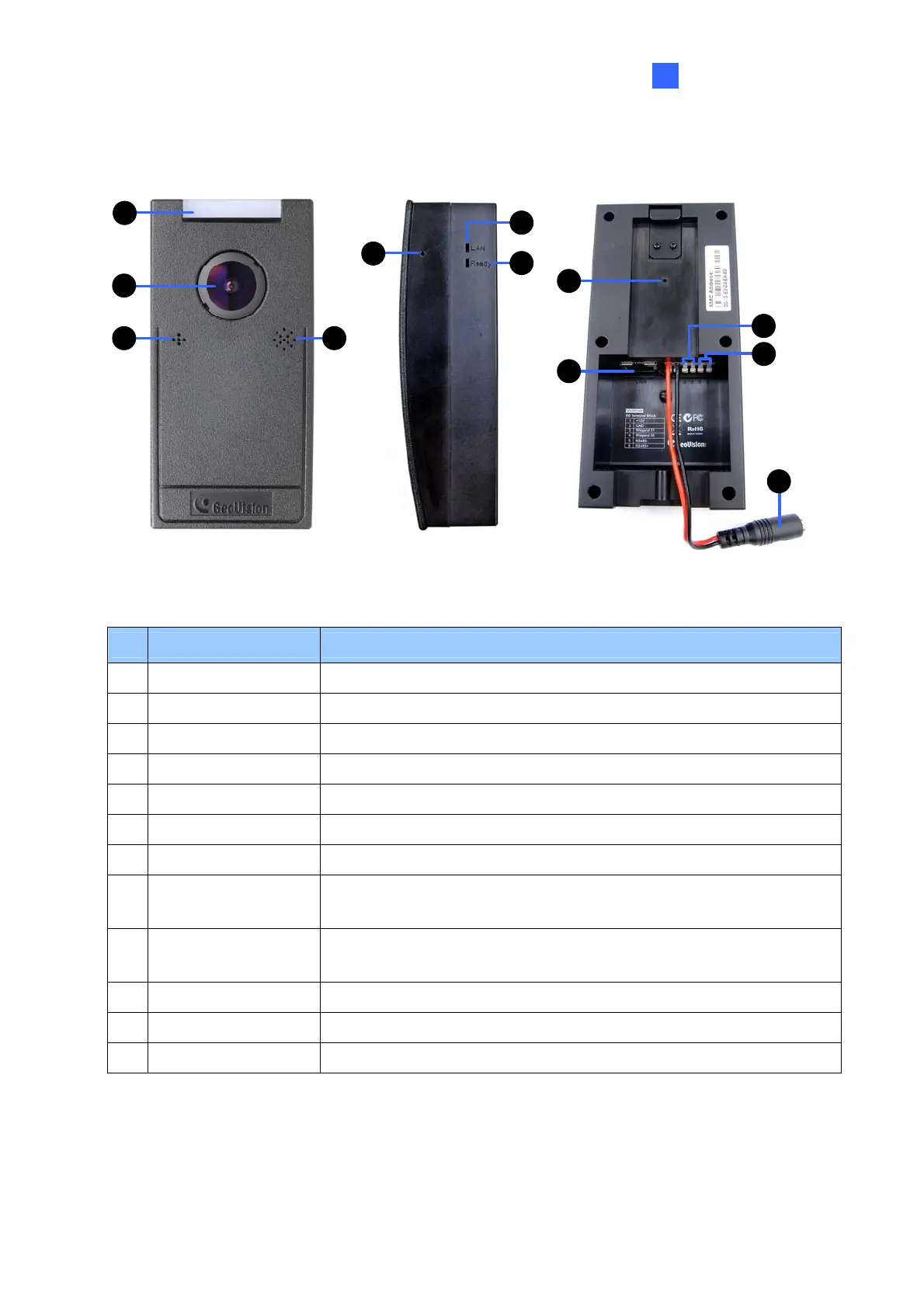
1.6 Physical Description
2
4
1
3
5
6
7
8
9
10
12
11
Figure 1-3
No. Name Function
1 LED Indicator Shows the status of the reader.
2 Lens Receives image.
3 Microphone Receives the sound from the camera.
4 Speaker Talks to the surveillance area from the local computer.
5 Beeper Generates sound to signal reader status.
6 Network status LED Indicates the network status.
7 Ready status LED Indicates whether the unit is ready for use.
8 Default Button
Resets all configurations to default factory settings. See 6.3
Restoring to Factory Default Settings.
9 Ethernet Port
Connects to network and allows network connection with GV-AS
Controller.
10 Wiegand Connects to a GV-AS Controller through Wiegand connection.
11 RS-485 Connects to a GV-AS Controller through RS-485 connection.
12 Power Cable Connects to power supply.
 Loading...