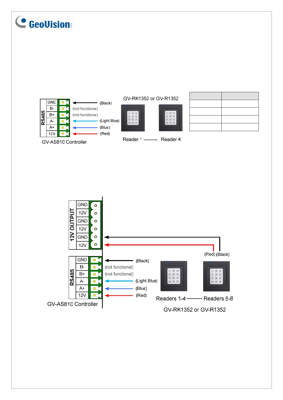
2.2 Connecting through RS-485 Interface
The following diagrams use GV-RK1352 and GV-AS810 Controller as an example. Up to
eight readers can be connected together to the RS-485 interface on GV-AS810 Controller.
Connecting four or less readers to GV-AS810 Controller:
Wire Color Function
Black GND
Light Blue RS-485 -
Blue RS-485 +
Red DC 7.5 ~ 12V
December
31, 2014
5
Connecting five or more readers to GV-AS810 Controller:
For readers five to eight, connect the RS-485 cable to the RS-485 interface on GV-
AS810 Controller and then connect the 12V power output and GND of the reader to a
12V DC power output on the controller.
 Loading...